
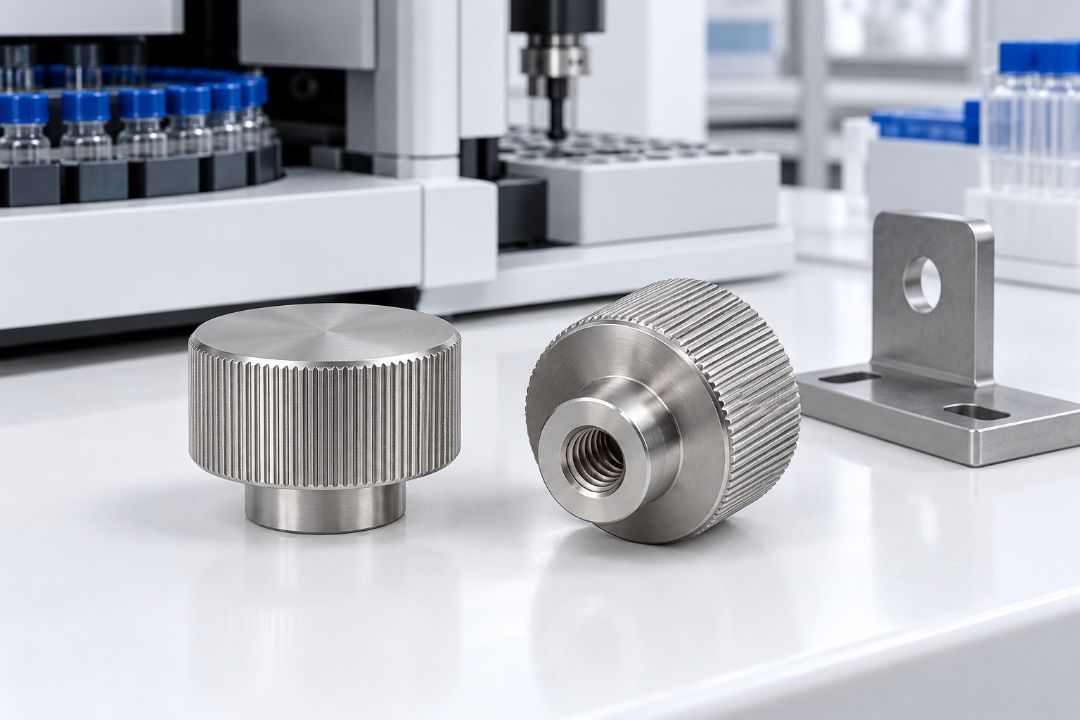
Define the knob within its mechanism
A threaded hand knob provides a user-operated interface to an adjustment or clamping arrangement. In medical laboratory equipment, the responsible designer must define what movement or contact the knob controls and how the setting is retained. A machined metal knob is not automatically a calibrated control, torque limiter or qualified locking device. This article concerns an equipment-side proposed component, not a surgical instrument or patient-contact accessory. Do not infer permissible force, adjustment accuracy or safety from a knurled rim and a thread that appears to fit another component.

Identify the thread and mating component
Specify thread form, size, pitch, handedness, fit requirements and the approved mating part rather than treating a female threaded opening as complete design information. A blind bore also needs its relevant depth and engagement requirements defined. Distinguish usable thread from lead-in and incomplete thread near the bottom. A mating screw that starts easily does not prove the entire specified interface. Resolve whether the mechanism should bear on a collar face, another shoulder or a separate component before manufacture. The supplier should not infer the intended contact from a sample knob alone.
Separate contact from accidental bottoming
The intended assembly contact must be defined independently from the thread's physical end. If a screw bottoms in a blind bore before the required shoulder seats, the mechanism may feel tight without making its intended contact. The approved design must establish the relevant relationships and assembly requirements. Do not deepen the bore or shorten a mating screw informally until a prototype seems acceptable. Authorized changes belong in controlled documents and inspection. This article does not prescribe universal engagement, tightening or wall-thickness values for every knob, material and equipment load arrangement.
Specify the actual grip geometry
A knurled outside surface can be manufactured in different ways and forms, so define the approved pattern, extent, edge condition and any relevant dimensional envelope. The cited industrial knob range illustrates that knobs are available with different materials and thread arrangements; it does not qualify this custom component. Avoid borrowing a catalog's grip, torque or ergonomic claims for a different design. The equipment team must evaluate operation with its actual users and conditions. An attractive knurl photograph does not establish suitable hand forces, cleanability or reliable retention of a selected setting.
Choose material and treatment deliberately
State the approved stainless grade, condition, stock form and evidence. A proposed 316L component should not silently become an unidentified stainless substitute because the finish looks similar. Any final treatment must follow an approved specification with relevant dimensional and surface checks. Material identity alone does not establish compatibility with every cleaning chemical or medical environment. Do not add lubrication, coating or thread treatment solely to improve a trial assembly without authorization. The complete material and surface pairing belongs to the controlled mechanism design, not an undocumented finishing preference.
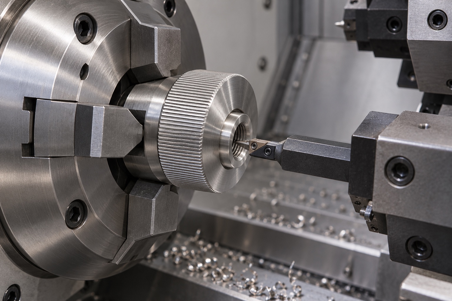
Plan turning from functional relationships
Choose machining references that relate the blind thread, collar and intended contact faces. Review setup transfers so a convenient chucking surface does not replace the installed functional reference. Workholding must support the component without damaging finished contacts or grip features. Control chips before internal threading and subsequent inspection. Cutting conditions depend on material, tool access and geometry rather than a universal recipe. Intermediate checks can confirm the sequence but do not replace final acceptance of the released part and any required treatment in the condition defined by the approved drawing.
Control knurling and remaining operations
Plan the grip-forming operation together with the rest of the route because it can affect holding, edge condition and the finished envelope. Keep any generated material away from internal threads and contact faces. Inspect the start and end of the pattern rather than judging only the middle of the rim. A proposed pattern change requires review when it alters the drawing requirements or assembly access. Do not use aggressive finishing to hide an incomplete feature. Cosmetic consistency and functional geometry should both follow the purchased specification, with their acceptance meanings kept distinct.
Finish internal and external edges
Inspect the thread entrance, blind bore, collar edge, top face and knurl boundaries for attached material or unwanted sharp transitions. Define edge requirements that preserve usable engagement and intended contact area. An exterior that feels smooth does not prove the blind opening is free from chips. Cleaning should follow the agreed scope and should not conceal a damaged thread. Keep markings outside critical contacts unless approved. A bright steel surface is not evidence of sterile supply, quantified cleanliness, suitable friction or achieved corrosion performance in the actual medical equipment environment.
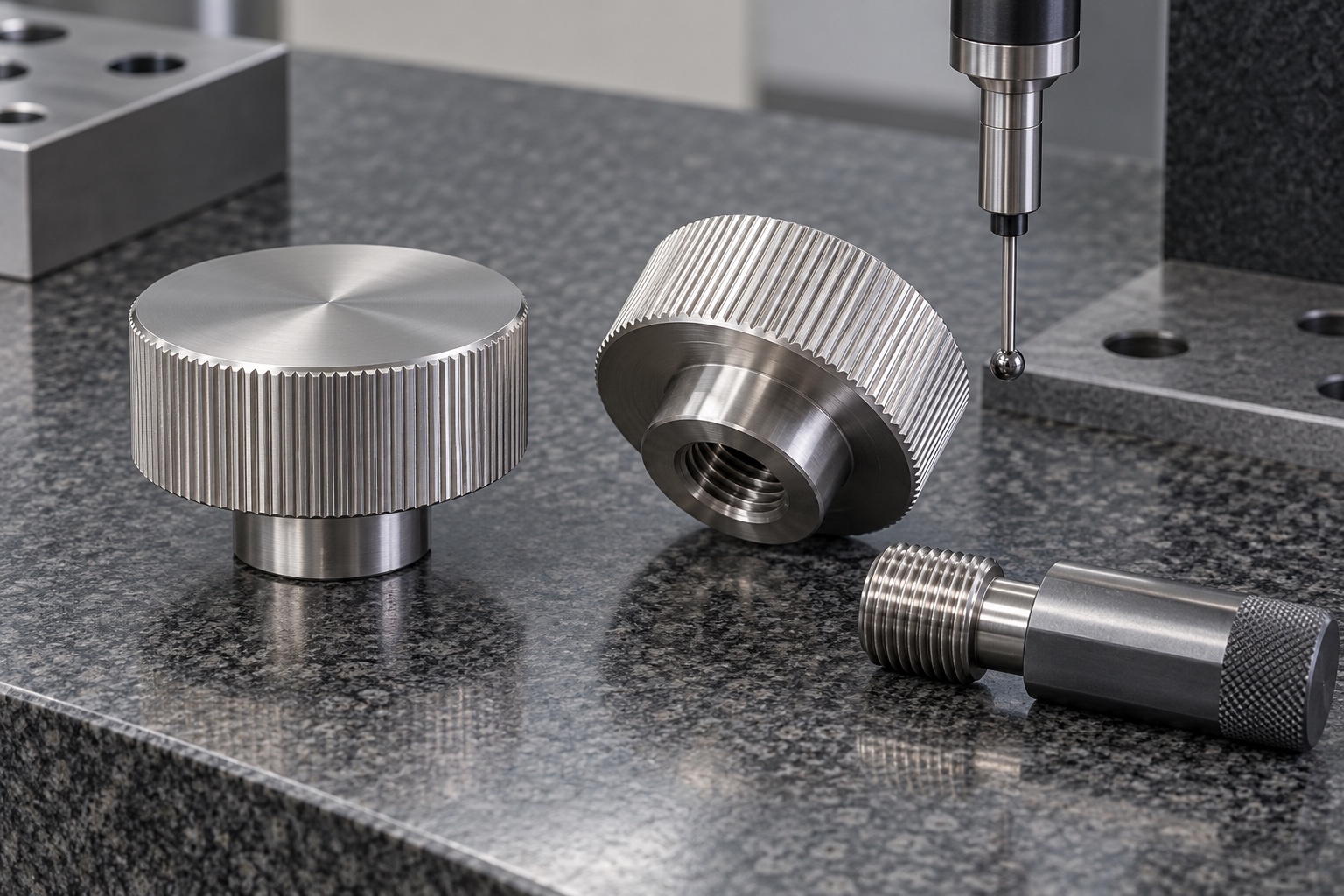
Inspect engagement and contact geometry separately
A thread gauge can address its defined characteristics but does not automatically verify collar height, contact-face relationship or every depth requirement of a blind bore. Map each drawing characteristic to a suitable method and accessible reference setup. Record the final surface state and inspection conditions. Identify any approved mating-component demonstration separately from dimensional acceptance. A single screw that feels satisfactory is not a universal gauge. Resolve inaccessible depth or ambiguous thread requirements before production rather than substituting outside diameter and a photograph of a successful hand assembly.
Bound mechanism trials and retention claims
An agreed trial may check insertion, travel, intended face seating and identified access with approved mating parts. Record component revisions, installation and any authorized surface treatment or lubrication. It does not by itself establish adjustment accuracy, clamping force, resistance to loosening, cycle life or equipment safety. Such matters require separately defined evaluation of the complete mechanism. Unexpected sticking or contact should be documented before modifying the knob or screw. A calibrated or torque-limited function should never be claimed for an ordinary custom hand knob without the required design and actual evidence.
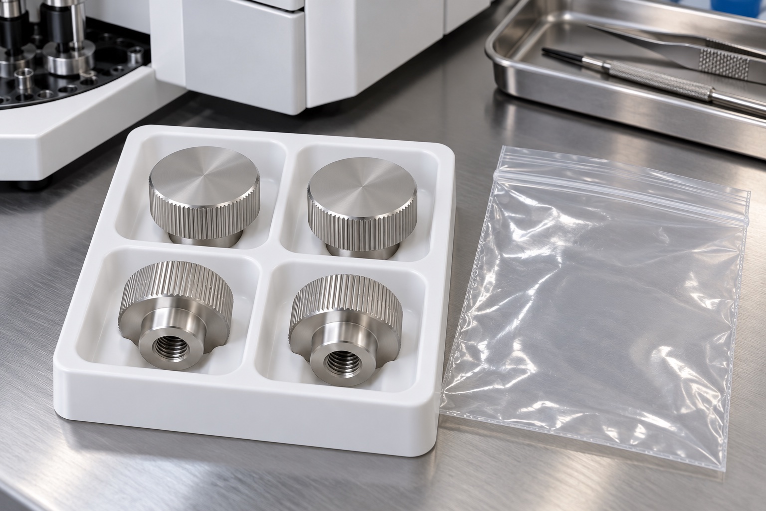
Protect grip, contacts and blind threads
Package knobs individually or separate them so the knurled edges cannot damage neighboring faces and loose hardware cannot strike the thread entrance. Keep unapproved fibers, adhesive and debris out of blind bores within the agreed cleaning scope. Ordinary transport packaging is not a sterile barrier. Preserve grade, lot, finish and revision identity with the shipment. Identify any demonstration mating screw separately from released production parts. The recipient should be able to distinguish the approved knob from a similar prototype or variant with another thread, collar or grip configuration before assembly.
Retain the complete adjustment baseline
A useful inquiry includes controlled model and drawing, thread and mating-component requirements, intended contacts, grip definition, material, surface process and inspection deliverables. Identify any assembly demonstration and keep mechanism-level qualification separate unless explicitly defined. Incorporate authorized prototype changes into revised documents. Review altered screws, collars, contact materials, lubrication or cleaning conditions before reusing earlier conclusions. This establishes a traceable turned component without suggesting that thread fit or an appealing knurled surface alone proves calibrated adjustment, a rated clamping force or the safety of the medical instrument.
Manufacturer background reference: www.elesa-ganter.com.
FAQ
Is a threaded knob automatically torque limited?
No. A conventional machined knob has no demonstrated torque-limiting or calibrated function merely because it can be turned by hand. Any claimed mechanism performance needs an approved design and separately defined evaluation with actual evidence.
Why distinguish engagement from blind-hole depth?
The total hole depth, usable thread and intended contact are different requirements. The approved design must prevent unintended bottoming from being mistaken for proper seating, with suitable inspection methods for the specified relationships rather than a universal engagement rule.
Can one mating screw replace thread inspection?
Not automatically. An identified screw may support an agreed fit demonstration, but it does not replace all thread, depth and contact-geometry requirements. Use methods tied to the controlled drawing and record the meaning and limitations of assembly checks.
Does 316L establish cleaning compatibility?
No. Grade identity is one design input. The complete surface state, mating materials, cleaning process and environment require application-specific review, and a stainless material certificate is not a blanket medical compatibility or finished-equipment qualification.
What should a knurl specification identify?
Identify the approved pattern, extent, finished envelope and edge condition as applicable to the design. A pattern change can affect manufacture, operation and surrounding access, so do not borrow ergonomic or torque claims from a different catalog knob.
Which changes require repeat-order review?
Review thread, mating screw, collar contacts, grip, grade, finish and any lubrication or cleaning requirements. Retain authorized revisions and keep previous fit observations separate from adjustment accuracy, retention and equipment-safety conclusions for a changed mechanism.

tanghangyun@oemach.com