
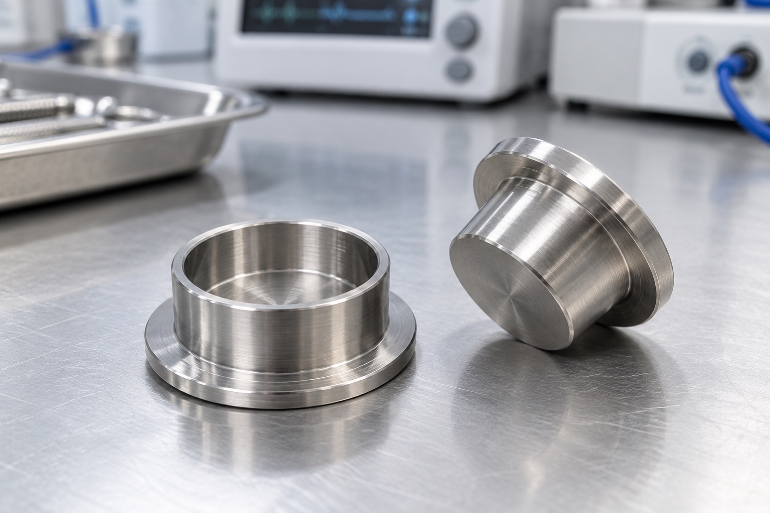
Define the seat rather than the complete mechanism
A spring locating seat establishes a contact and positioning interface for an approved spring inside medical equipment. A shallow cup may locate one end, but it is not the spring, actuator, restraint or complete load-bearing mechanism. The equipment designer must define how the cup, spring and surrounding parts work together. This article addresses a proposed equipment-side turned component, not an implant or patient-contact device. Start with controlled spring and assembly documents. A cup photograph or a loose spring that fits inside it does not define the functional requirements or the acceptance evidence needed for production.

Obtain the approved spring-end configuration
Identify the actual spring revision, end configuration, relevant diameters and installation arrangement. The referenced spring manufacturer discusses end squareness and seating, providing context for treating the contact as an assembly requirement rather than a generic circular pocket. Do not transfer one catalog spring's properties or load statement to a custom cup. The responsible program must specify the intended contact and movement. A supplier should not choose a universal pocket clearance or preload from an isolated spring sample, particularly when that sample has no traceable identity or approved role within the final medical equipment mechanism.
Relate the pocket to functional mounting references
The pocket floor, locating wall and mounting face have different functions and need explicit relationships. Identify which surfaces establish the cup's installed position and which merely provide clearance. An acceptable pocket diameter alone does not establish floor position or alignment to the surrounding mechanism. The designer must set relevant dimensional and geometric requirements for the actual assembly; this article offers no universal tolerance. A convenient turned outside surface should not become the inspection datum by habit when the installed position is established by another face, flange or approved locating feature.
Separate contact position from spring force
Pocket depth and contact geometry affect where the spring end sits, but dimensional acceptance alone does not establish installed force, stroke, life or mechanism safety. Those conclusions require the approved spring specification, full assembly arrangement and separately defined evaluation. The equipment team must identify the relevant installed conditions and acceptance criteria. A supplier should not calculate a device load from a generic cup drawing or a hand-compressed spring. Preserve the exact cup and spring revisions used in any demonstration, and review changes before transferring previous assembly conclusions into another configuration or operating condition.
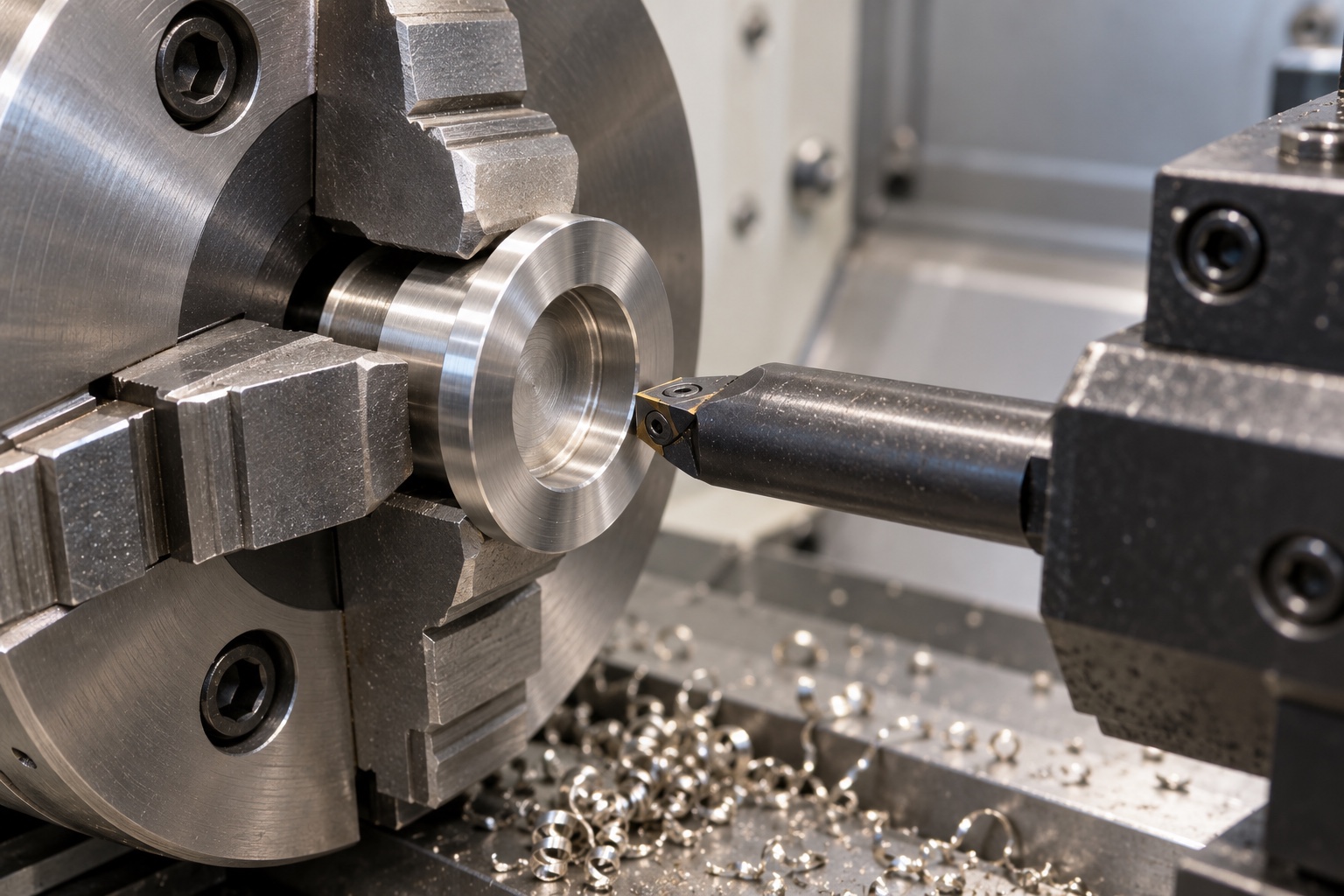
Review floor transitions and surrounding clearance
Examine the pocket floor, wall transition, entrance and any locating pilot together with the approved spring end and mating parts. An internal radius can change the available contact region even when the diameter is correct. Review tool access before manufacture and obtain approval for any proposed relief. Identify the actual travel and insertion envelope rather than checking only a stationary loose fit. Do not remove material informally to make an unapproved spring enter. Accepted changes must become controlled geometry and inspection requirements instead of remaining a manually modified prototype that is difficult to repeat.
Specify material and final surface condition
316L can be a proposed material, but its name is not a universal promise of corrosion resistance, contact durability or medical certification. Specify the approved condition, stock form and evidence. Consider the actual material combination and environment within the responsible equipment design. If passivation or another final process is required, define documentation and final-condition inspection. Keep markings away from functional contacts unless approved. A polished cup is not automatically a quantified clean component, and a material datasheet does not by itself establish compatibility with the equipment's cleaning process, spring material or long-term operating conditions.
Plan turning around the contact relationship
The route should preserve the pocket, floor and mounting-reference relationships through turning and any additional operations. Establish suitable workholding without damaging a finished contact or forcing a thin flange into shape. Control chips and consider access to the blind pocket before selecting the process. Cutting conditions depend on the actual material condition, tools, machine and geometry, so one universal recipe is inappropriate. Intermediate checks can help confirm the route, but final acceptance must address the completed part after required treatment, not a partly machined cup that happens to accept one convenient sample spring.
Finish contact edges without altering the design
Examine the pocket entrance, floor transition, flange edge and any pilot shoulder for unwanted burrs or attached material. Define edge conditions that preserve the approved spring contact. Uncontrolled polishing or scraping should not be used to hide a fit problem or reshape a floor without documentation. Cleaning should follow the purchased scope and maintain contact integrity. Visual inspection may complement the plan, but a shiny surface is not a verified texture or wear result. Distinguish any separately specified surface requirement from geometric acceptance rather than treating appearance as evidence for both functions.
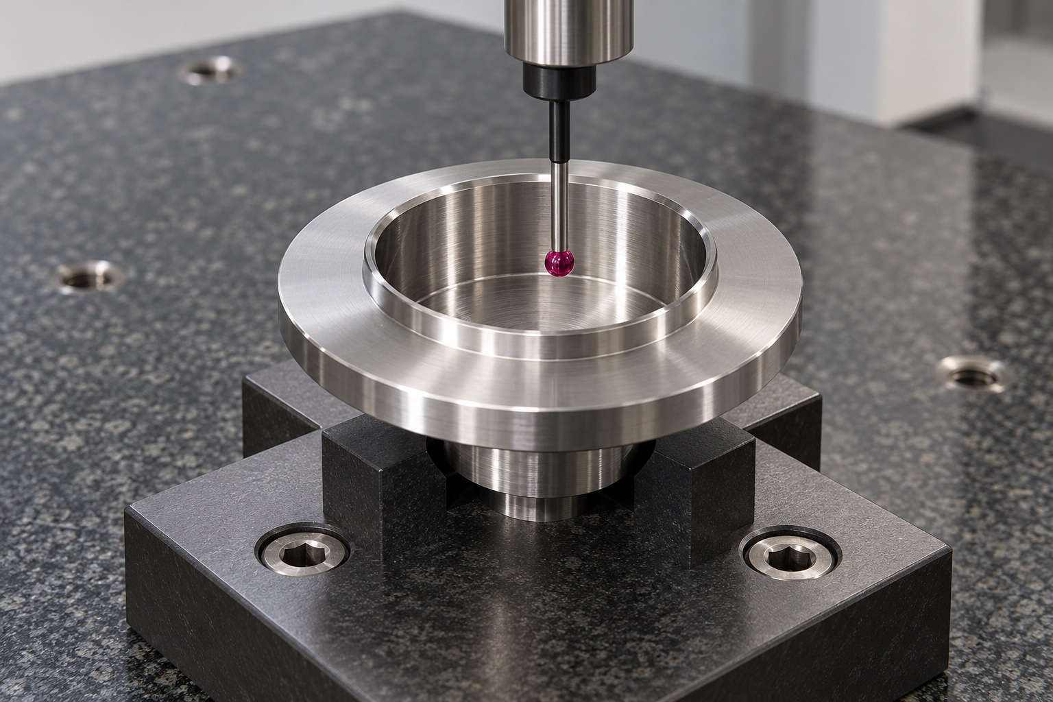
Measure the specified pocket and reference features
Map numbered drawing requirements to methods that can reach the pocket and evaluate its relationship to the mounting features. An outside diameter and overall-height report is incomplete when acceptance depends on the internal floor and contact geometry. Record support, reference arrangement and final treatment condition. A trial spring fit has only the acceptance meaning explicitly assigned to it and does not replace every drawing requirement. Resolve inaccessible measurements before production. If installed or loaded geometry must be assessed, define that separately instead of allowing a fixture to conceal the specified free-condition component geometry.
Keep assembly trials limited and controlled
A documented trial may check insertion, seating and agreed clearances with identified approved components. The responsible program must define safe handling and any loaded procedure; a basic component article does not provide instructions for compressing or retaining an unspecified spring. Record cup, spring and mechanism revisions and the exact checks performed. Such a trial does not establish operating load, fatigue life or device safety without separate evaluation. Unexpected contact should be documented before changing the cup or mating hardware, and an unrecorded hand-fitted sample must not become the repeat-production acceptance standard.
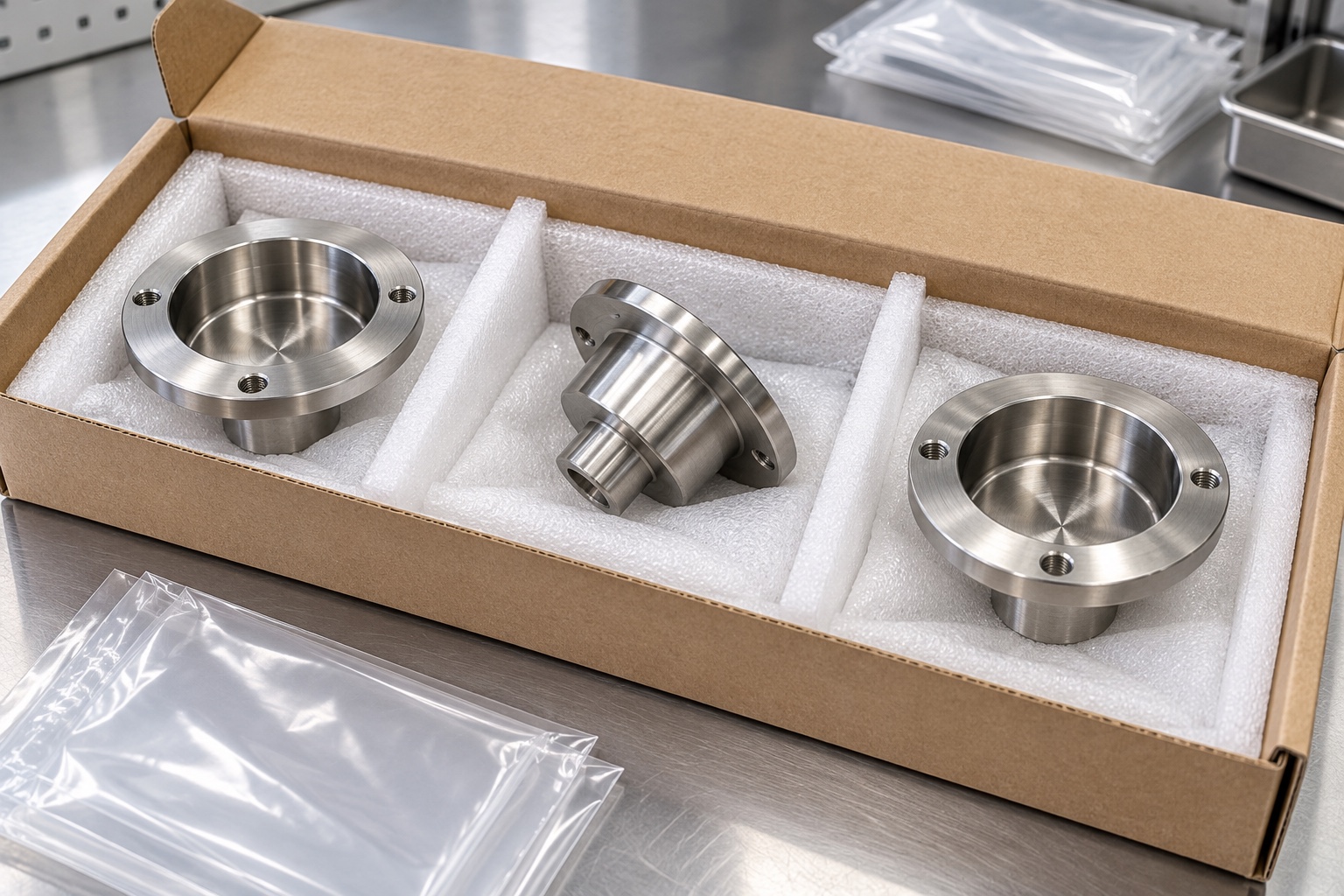
Protect the blind pocket during shipment
Packaging should keep the floor, pocket entrance and mounting contacts from striking neighboring metal parts or collecting uncontrolled residue. Support the flange or approved regions without loading thin features. Keep any separately supplied springs or mating samples identified by their production or trial status. Ordinary protective bags are not sterile supply or evidence of a quantified cleanliness level. If a specific cleanliness criterion is purchased, define its verification. Material-lot and revision records should accompany the cup so receiving personnel can distinguish the accepted configuration from a prototype or a similar-looking part made for another spring.
Maintain a traceable repeat-order package
A complete inquiry includes the approved component drawing and model, spring documents, contact arrangement, mounting references, material condition, final process and inspection deliverables. Identify any requested assembly trial and keep load, life and device-level qualification separate unless explicitly defined. Incorporate authorized prototype changes into controlled documents. Review altered spring ends, mating materials, mechanism travel or installation conditions before reusing previous observations. This makes the locating seat a clear manufactured interface with traceable geometry and evidence, without asking a CNC supplier to invent the performance or safety requirements of the complete medical equipment mechanism.
Manufacturer background reference: www.leespring.com.
FAQ
Does a spring that fits the cup prove correct operation?
No. A loose fit demonstrates only that limited observation. Contact geometry, mounting references, spring identity and the full mechanism matter. Load, travel, life and safety require their own approved specifications and evaluation for the actual equipment configuration.
Why identify the spring-end configuration?
The end contact and surrounding envelope affect how the spring seats. Use approved spring and assembly documents rather than copying a catalog property or choosing a universal clearance from an unidentified sample that happens to enter the pocket.
Does pocket depth alone establish installed force?
No. Force depends on the approved spring and complete installed arrangement. A dimensional cup report does not replace spring specifications or a separately defined mechanism evaluation, and a supplier should not invent preload from a generic component drawing.
What should be inspected beyond the outer diameter?
Inspect the drawing-defined pocket, floor, contact transitions and their relationship to mounting references. Choose suitable methods and document support and final condition. A spring fit check has only its explicit assigned meaning, not universal dimensional acceptance.
Can an assembly trial be included?
Yes, with identified approved parts, a defined procedure and explicit insertion, seating or clearance checks. The responsible program must define handling and any loaded evaluation. A basic trial remains separate from fatigue, load and complete medical-device qualification.
Which changes require review for repeat production?
Review spring identity and ends, pocket geometry, mounting, material, treatment and mechanism installation. Preserve approved revisions and evidence rather than transferring earlier seating or performance conclusions automatically to a changed spring or equipment configuration.

tanghangyun@oemach.com