
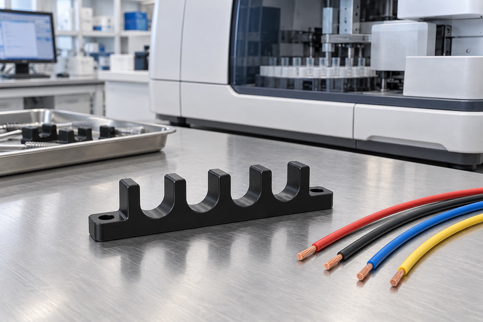
Define guidance rather than electrical protection
An internal cable guide comb separates and locates selected cables inside medical equipment. Its open slots may organize a fixed routing point, but the comb alone does not establish electrical insulation, strain relief, fire performance or device safety. The responsible equipment team must define its role within the complete wiring arrangement. This article addresses a machined equipment-side component, not a connector, cable carrier system or patient-contact item. Start by identifying the cables, installation sequence, nearby metalwork and intended contact surfaces before assigning material and dimensional requirements to the part.

Obtain approved cable and connector information
A cable's nominal diameter is not a complete routing specification. Obtain the approved cable construction, jacket information, manufacturing variation, connector envelope and applicable installation instructions. State whether a connector must pass through the route or the cable can be placed laterally into an open slot. Separate power, signal or other cable groups according to the equipment design rather than a supplier's assumptions. An unidentified sample wire should not establish the production interface. Keep the accepted cable revision and supplier information associated with any assembly trial and with future changes to the instrument.
Relate slot geometry to the actual route
Specify slot width, depth, entry shape and location relative to the installed mounting references. Identify the intended jacket contact and regions requiring clearance. An open U-shaped slot does not necessarily retain a cable under every load or motion, and should not be described as a clamp unless that function is designed and evaluated. A smooth-looking bottom does not establish an acceptable contact profile. Review the route on both sides of the comb, because a locally adequate slot can still lead into an unsuitable bend, connector approach or interference with another part.
Keep bend radius and strain relief explicit
The referenced cable-management manufacturer discusses bend radius and strain relief as elements of a complete routing arrangement. That background is a reason to obtain application-specific cable instructions, not to copy a carrier's rating onto a custom comb. This article provides no universal bend-radius multiplier, pull force or cable life. The equipment designer must determine whether the comb merely guides, supports or forms part of a separately evaluated restraint. A part that meets its drawing does not prove that cable connections are protected from assembly loads, repeated movement or other operating conditions.
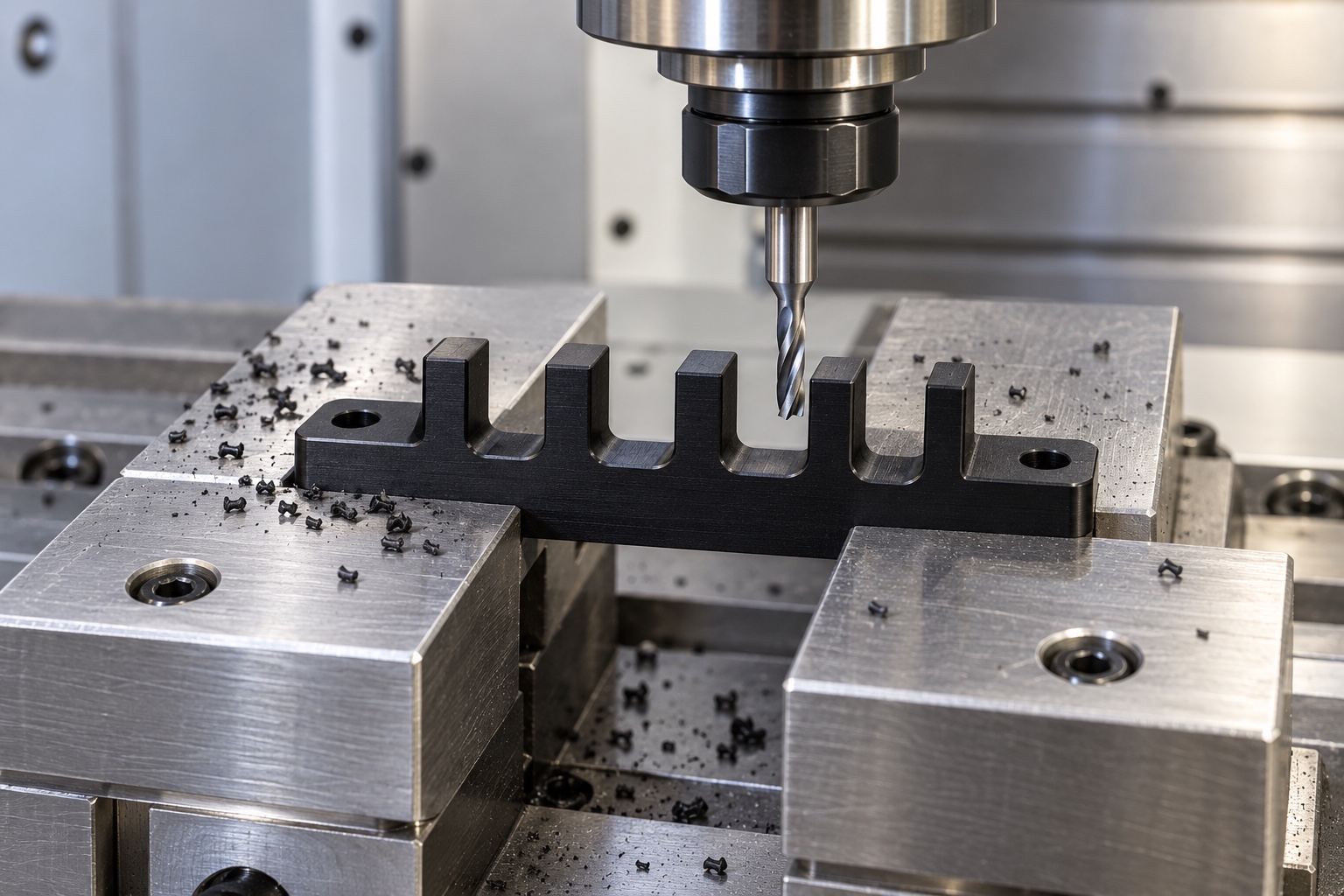
Specify the actual polymer grade
Black POM identifies a proposed material family and appearance, not a complete purchasing specification. The drawing should identify the approved grade, stock form and required documentation. Color alone does not prove identity, electrical behavior, flammability classification or cleaning compatibility. Keep material-lot evidence with the components after cutting and machining. A change intended to improve supply or cost requires design review before production. The machining supplier can preserve an approved material choice, while the responsible program evaluates whether that material is appropriate in the actual thermal, electrical and environmental configuration of the instrument.
Plan support around the open slot geometry
Machining several open slots leaves slender fingers that should not be distorted by workholding or finishing. Establish broad support and a route that preserves the mounting base and slot relationships after material removal. Control chips at fixture contacts and maintain access to slot bottoms and mounting features. Cutting conditions depend on the grade, tools, equipment and actual geometry. Do not prescribe a single universal speed or clamp force. Intermediate checks help confirm the route, but acceptance must address the completed comb in the specified free or installed condition rather than a shape imposed by a fixture.
Finish every cable-contact transition
Pay deliberate attention to slot mouths, bottom transitions and the two faces through which a cable enters and leaves the guide. Attached polymer material or a sharp local transition can be missed when only overall dimensions are checked. Specify the required edge condition and inspection approach. Uncontrolled scraping, heating or polishing should not become a hidden method of making a cable fit. Keep identification markings away from contact areas unless approved. Appearance inspection can be useful, but does not replace a defined profile requirement or demonstrate quantified abrasion resistance over the equipment's service life.
Preserve mounting and routing references
The comb's mounting face and holes establish how the slots sit in the equipment. Relate the slot pattern to those functional references rather than a convenient unmachined edge. Review screw-head and tool access as well as surrounding cover clearances. State any specified condition for tightening or inspection; a small polymer component can respond differently under installation loads than when measured freely. The supplier should not invent a torque. If a separate retaining cover is used, its approved geometry and assembly relationship must be included rather than assumed from the open comb alone.
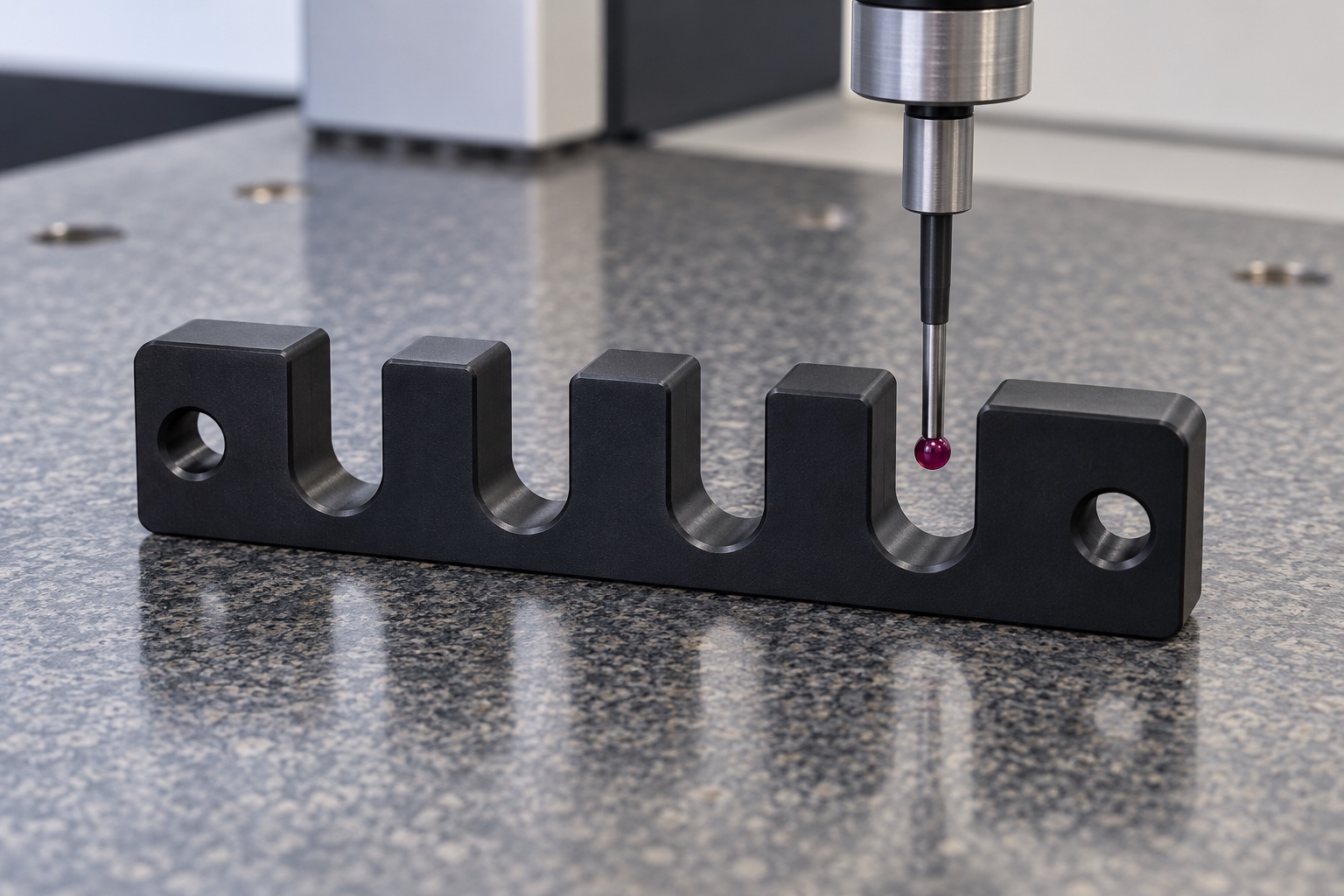
Measure the features that affect contact
Map drawing requirements to suitable inspection methods, including access to slot widths, locations and the specified contact transitions. Measuring pressure and support should not deform slender fingers and create a misleading result. Record references, support condition and any environmental conditioning required by the project. A report showing only overall length and mounting-hole spacing is incomplete when the controlled cable interface lies inside the slots. Resolve inaccessible measurements before production. A sample cable fit can complement a plan only when its identity and acceptance meaning are explicitly defined in the controlled inspection package.
Separate routing trials from qualification
A documented trial may check placement, assembly access and agreed clearances with identified cable assemblies. Record the comb revision, cable identities, connector arrangement and installed supports. A photograph of neatly arranged wires does not demonstrate insulation integrity, electromagnetic compatibility, flammability, cable endurance or medical-device safety. Those matters require separate approved evaluation. If unexpected jacket contact or interference is found, document it before modifying the part. Do not carry trial observations into a changed cable or enclosure without review merely because the guide looks unchanged and the wires still fit by hand.
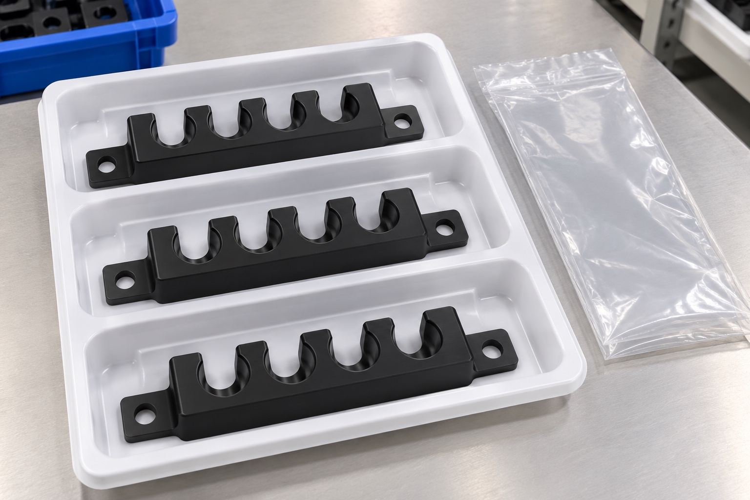
Protect slots and preserve material identity
Packaging should separate combs so that the fingers and cable-contact edges cannot rub or interlock during shipment. Avoid protective materials or labels that leave uncontrolled residues in the slots. Keep grade, lot and revision information with the delivery. Ordinary transport protection is not sterile supply or evidence of a quantified cleanliness level; any purchased cleanliness requirement needs an explicit verification method. Receiving personnel should be able to distinguish an accepted production component from a prototype, substituted polymer or trial part before installing it inside a controlled medical equipment assembly.
Define a reproducible procurement scope
A complete inquiry includes the approved model and drawing, polymer grade, cable identities, routing arrangement, mounting hardware and inspection deliverables. Identify any assembly trial and keep electrical, endurance and device-level qualification separate unless its scope and responsibility are defined. Preserve authorized prototype changes in controlled documents. Review altered cables, jackets, covers or operating conditions before reusing previous conclusions. The result is a traceable guide component with defined geometry and evidence, without unsupported promises that a machined comb alone protects connectors, validates insulation or qualifies the complete medical instrument's wiring architecture.
Manufacturer background reference: www.igus.com.
FAQ
Is an open cable comb automatically a strain-relief device?
No. Guidance, retention and strain relief are different functions. The equipment designer must define the intended role and evaluate the complete cable and connection arrangement. Passing a dimensional inspection does not establish a cable pull rating or service life.
Why specify cable identity instead of diameter alone?
Jacket construction, connector geometry, variation and installation instructions can affect the route. Preserve the approved cable information and review substitutions rather than assuming every cable with a similar nominal diameter is interchangeable in the same comb.
Does black POM establish electrical or fire compliance?
No. Specify the approved material grade and documentation. Color and generic polymer identity do not demonstrate electrical insulation, flammability performance or medical-device suitability. The actual equipment configuration requires its own applicable evaluation and acceptance evidence.
What should be inspected at each slot?
Inspect the drawing-defined width, location, depth and relevant contact transitions using appropriate methods. Control support and measuring force, and examine both entry faces. A cable that can be pushed into a sample slot does not verify all those requirements.
Can an assembly trial verify cable endurance?
Not by itself. A simple trial covers only the explicitly agreed placement, access and clearance checks. Endurance, insulation integrity and equipment safety require separate procedures, conditions and criteria defined by the responsible program for the actual configuration.
What changes require a repeat-order review?
Review cable identity, jacket construction, connector envelope, routing, mounting, polymer grade and surrounding covers. Preserve approved revisions and authorized prototype modifications instead of transferring previous trial or qualification conclusions automatically to a changed installation.

tanghangyun@oemach.com