
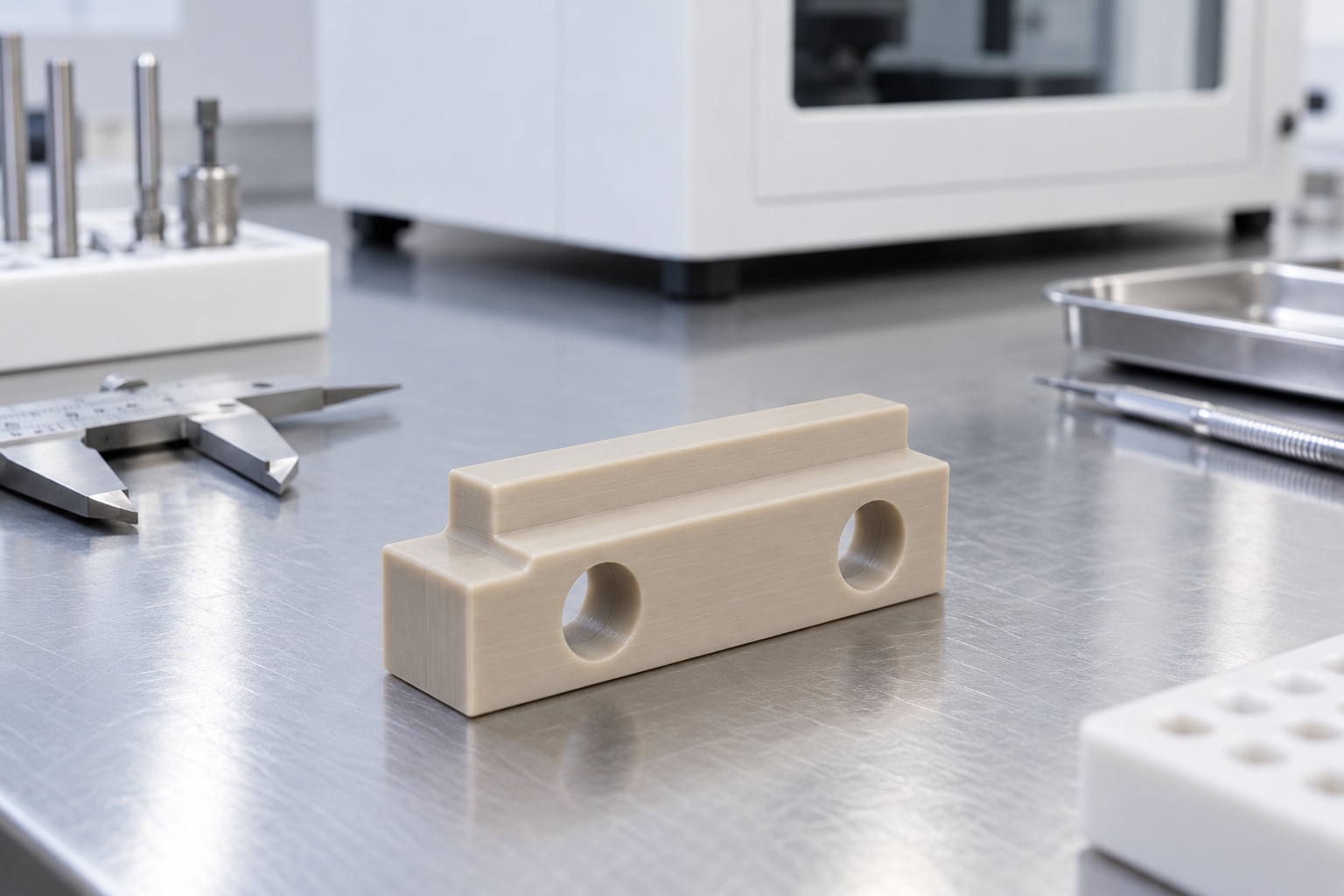
Define the spacer's intended role
A polymer spacer can establish separation and mounting geometry between equipment components. It may be proposed as part of an insulating arrangement, but a machined block alone does not establish electrical protection or compliance of a medical instrument. The responsible design team must define its mechanical role and any electrical function within the complete assembly. This article concerns equipment-side CNC geometry, not a certified insulation system, implant or fluid-contact component. Begin by distinguishing the contact faces, locating shoulder, mounting holes and surrounding parts before assigning material, dimensional or verification requirements to the spacer.

Specify the actual PEEK grade
PEEK is a material family, not a complete purchase specification. The referenced polymer manufacturer distinguishes particular grades and their properties, illustrating why a drawing should identify the approved material rather than rely on a generic name or beige appearance. Fillers, raw material form and processing history can matter to the intended application and machining route. Obtain the required grade and documentation before production. Do not transfer a typical material datasheet value directly into a claim about a machined part or complete instrument. Application suitability requires the actual design conditions and appropriate supporting evidence.
Separate stack height from outside size
The functional separation may be controlled by two contact faces rather than by the largest outside dimension. A step or shoulder can create a second height that needs its own relationship to the mounting references. Identify which surfaces establish the installed stack and which remain clear. A block that meets its overall thickness can still position a mating component incorrectly if it seats on an unintended edge. Define relevant parallelism, height or other requirements where the design needs them, and avoid assuming that every external face has equal functional importance merely because it appears in the model.
Review screw and washer contact
Mounting holes must suit the approved fastener arrangement and surrounding parts. A clearance hole does not automatically define screw-head contact, washer support or final clamp condition. Review whether hardware contacts the intended faces and whether a shoulder obstructs assembly access. Tightening requirements belong to the actual equipment design; this article supplies no universal torque or clamp force. A polymer component can respond differently under installation loads than during an unloaded dimensional check. State any required installed-condition evaluation separately and do not let a supplier infer the complete fastening arrangement from a hole diameter alone.
Keep electrical evaluation separate
If the spacer has an electrical role, the responsible program must define the applicable insulation requirements and verification within the actual instrument. Geometry, hardware, environment and contamination conditions may matter beyond a material datasheet. No universal insulation distance, test voltage or protection rating can be inferred from this article. A dimensionally accepted PEEK block should not be marketed as proof of medical electrical compliance. The machining supplier can preserve specified material identity and geometry, while the equipment team evaluates the complete configuration using the standards, procedures and acceptance criteria appropriate to that application.
Choose references that remain accessible
The manufacturing reference scheme should connect the spacer's contact faces, shoulder and holes to the installation requirements. A convenient raw material edge should not silently replace the approved functional reference. Plan setup transfers so the relevant stack-height relationship survives machining from more than one direction. Inspection fixtures must support the part without forcing it into an apparently correct shape. If the drawing requires a free-condition measurement, state that clearly. Any separately defined installed or loaded condition needs its own arrangement and acceptance meaning rather than being substituted for the unloaded component's specified geometry.
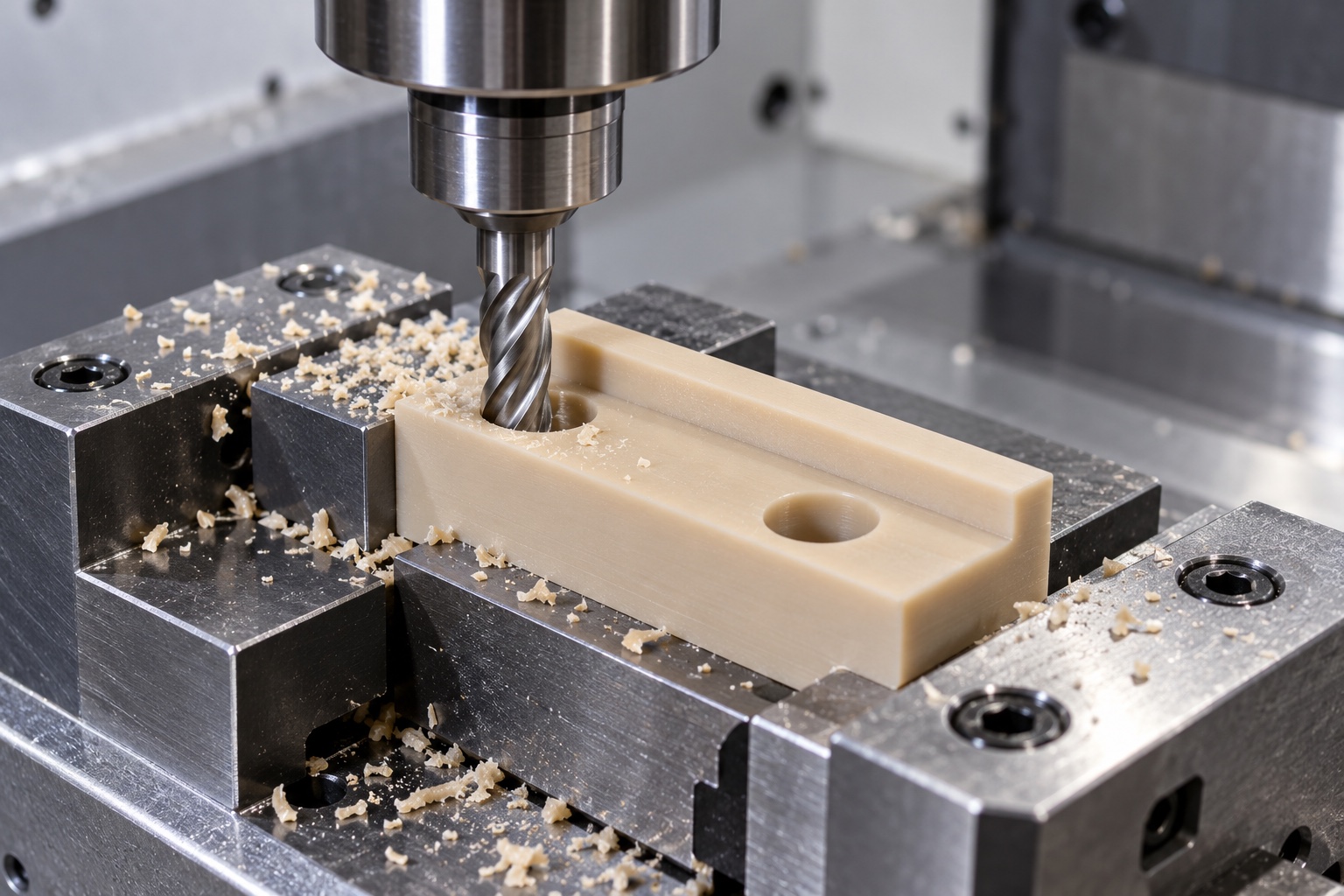
Machine the polymer with controlled support
Workholding should provide stable support without excessive pressure on sensitive sections. Material removal around a step can change local stiffness, so inspect the released condition where required rather than judging the result only inside the fixture. Tool choice and cutting conditions depend on grade, geometry and equipment; no single speed or feed applies to every spacer. Control debris at setup contacts and preserve sufficient access to functional faces. Intermediate checks can help establish a repeatable route, but they do not replace acceptance of the final component under the drawing-defined inspection condition.
Finish holes, shoulders and edge transitions
Polymer machining can leave attached material at hole exits or narrow steps. Define a removal process that preserves the approved contact geometry. Uncontrolled scraping, polishing or heating should not become an unrecorded way to make one assembly fit. Inspect both entrances and exits of through-holes and the transition beside any locating shoulder. An attractive surface does not establish a verified texture or acceptable electrical condition. Cleaning should follow the documented material and purchase requirements, and should not conceal a damaged contact face or replace a required dimensional check with an appearance judgment.
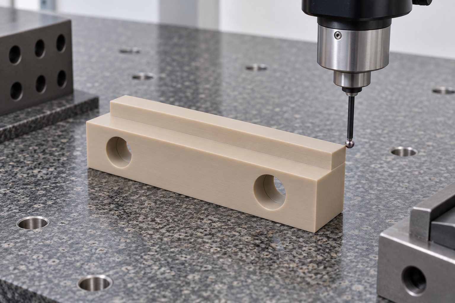
Measure under an agreed polymer condition
The inspection plan should address the part's condition and the force applied by measurement tools. Avoid deforming a thin feature while measuring the dimension intended to describe its free shape. Appropriate methods may differ between contact-face relationships and accessible hole geometry. Record references, support arrangement and any required environmental conditioning. An overall thickness result alone is not a complete report if the shoulder and mounting pattern control the installed separation. Where a feature cannot be reached reliably, resolve the method before production rather than substituting an easy dimension unrelated to the actual interface.
Define mechanical trials without extending claims
A controlled trial can check seating, fastener access and agreed clearances using identified mating parts. It does not establish insulation performance, long-term load behavior or medical-device safety without separate evaluation. Record the spacer revision, material grade, hardware and assembly configuration used. If an unexpected contact occurs, document it before changing the shoulder or hole arrangement. Hand fitting one sample can hide a missing design requirement. Any accepted modification should enter controlled documents, and results should not be transferred automatically to a different grade, fastener or installation merely because the spacer's general outline remains similar.
Protect surfaces and material identity
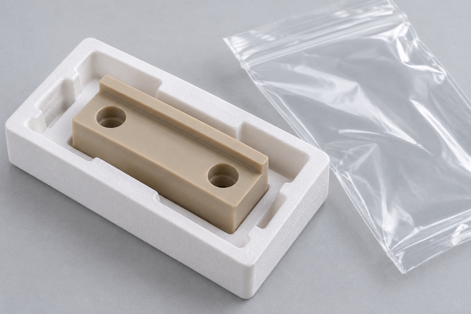
Separate finished spacers so contact faces and shoulders do not rub or collect debris during transport. Protective packaging must match the agreed assembly and cleanliness scope; an ordinary bag is not evidence of sterile supply. If a quantified cleanliness criterion is required, specify its verification rather than relying on visual appearance. Preserve grade, lot and revision information with the shipment. Avoid unapproved labels or markings on functional contact surfaces. Receiving staff should be able to distinguish the accepted component configuration from a visually similar polymer substitute or trial part before it enters the equipment assembly process.
Make the purchase scope explicit
A useful inquiry includes the approved drawing, model, grade, raw material requirements, mounting hardware, stack-height references and inspection deliverables. Identify any requested mechanical assembly trial and keep electrical qualification separate unless its scope and responsibility are explicitly defined. Retain authorized prototype changes and approved revisions for repeat production. Review altered grades, hardware, environment or installation before reusing earlier conclusions. This approach makes the spacer a controlled manufactured interface with traceable evidence, without inventing claims about insulation, clinical suitability or safety that require evaluation of the complete medical instrument rather than a machined polymer block alone.
Manufacturer background reference: www.victrex.com.
FAQ
Does specifying PEEK establish medical electrical compliance?
No. Material identity and dimensional acceptance do not qualify the complete insulation arrangement. The responsible equipment program must define and perform the applicable electrical and device-level evaluations for the actual configuration.
Why specify the grade instead of color?
Appearance does not establish polymer identity or equivalence. Specify the approved grade, raw material form and documentation, and review any substitution before production rather than treating similarly colored blanks as interchangeable.
What controls the installed stack height?
The approved design identifies the actual contact faces and their relationships to shoulders, holes and mounting references. Overall outside thickness alone may not establish the separation between the installed mating components.
Who defines the fastening conditions?
The responsible equipment design team approves the hardware, contact arrangement and installation requirements. A machining supplier should not invent universal tightening torque or assume a complete assembly condition from a clearance-hole diameter.
Can an unloaded dimensional check prove long-term performance?
No. It verifies only the specified measurement condition. Load behavior, insulation performance and equipment safety need separate evaluation with approved conditions and acceptance criteria beyond the component's dimensional report.
What changes require a repeat-order review?
Review changes to material grade, geometry, hardware, installation or environment. Preserve approved revisions and authorized prototype modifications so earlier fit or qualification conclusions are not silently transferred to a different configuration.

tanghangyun@oemach.com