
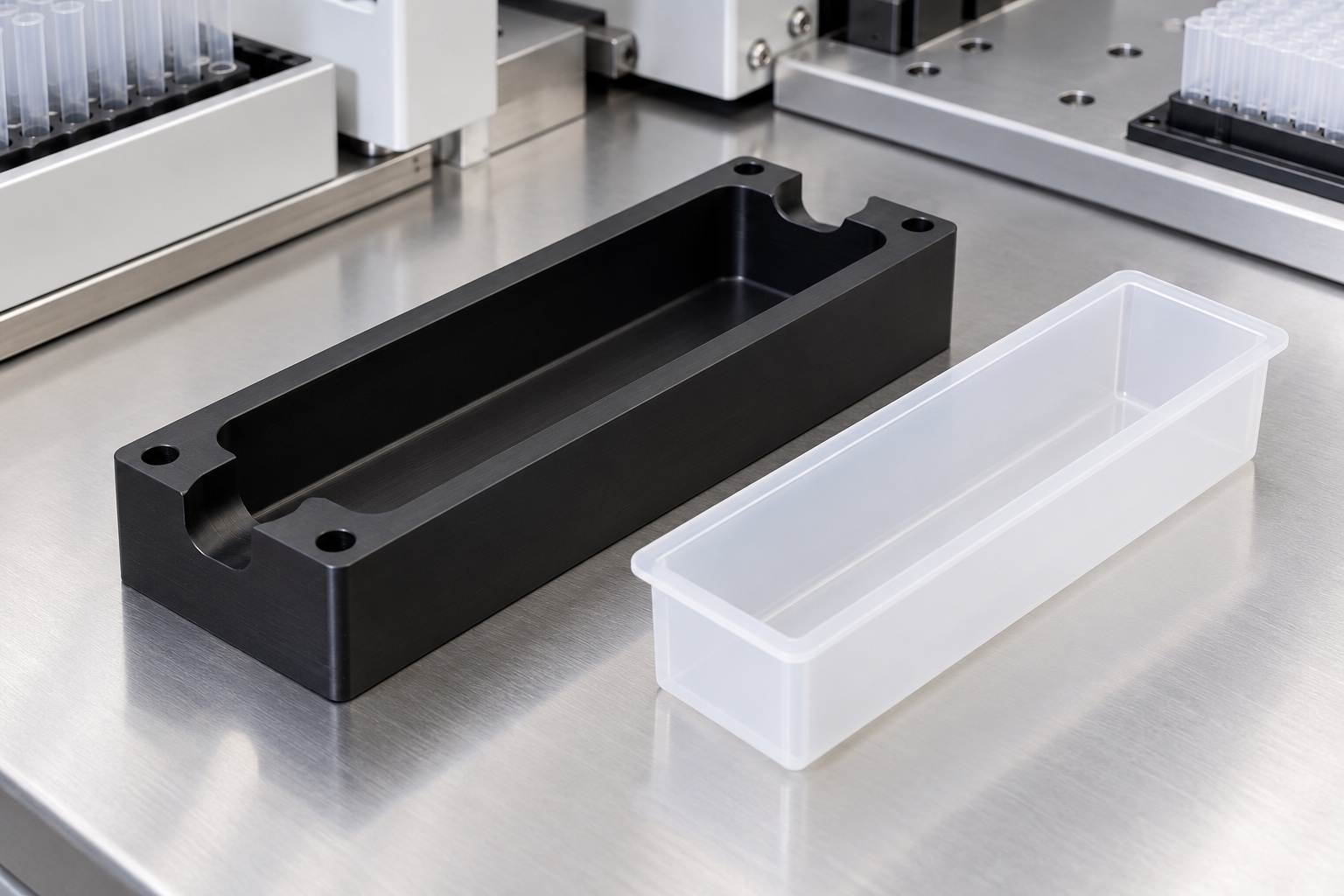
Separate the holder from the reagent container
A machined reservoir holder supports an approved consumable within laboratory equipment. The container holds the reagent; the surrounding support can remain outside the intended fluid path. That distinction must be confirmed for the real assembly rather than assumed from a photograph. This article addresses the equipment-side holder, not a sterile reagent vessel or validated assay component. The referenced consumables manufacturer offers platform-specific trough arrangements, illustrating why interface selection matters. A custom support needs its own approved drawing and review, and does not inherit a consumable's purity claims or equipment compatibility.

Obtain the consumable's complete outside geometry
A nominal reservoir capacity does not define the holder cavity. Obtain the approved external geometry, flange shape, bottom contour and permitted variation for the selected container. Include any label or feature that can interfere with insertion. A single empty sample can help discuss the interface but should not replace controlled requirements. Define whether the design supports the bottom, the flange or specific contact regions. Mixing those support assumptions can change the container's installed height. The equipment team must approve the intended contact arrangement before the machining supplier selects cavity geometry or inspection limits.
Distinguish support from lateral location
A cavity floor can support the reservoir while side features establish its lateral position. Other walls may provide clearance rather than contact. Show these roles in the drawing so a supplier does not turn every surface into an unintended tight fit. A thin consumable may deform if it is forced into an overconstrained holder, even when the holder itself appears rigid. Identify the insertion direction and intended seating sequence. Any retention feature should be reviewed together with removal access and the container's allowed contact areas, not added informally after the first trial.
Keep handling and instrument access clear
The holder should leave room for the approved loading, removal and equipment movement. Finger-access cutouts can assist handling, but their shape and location must preserve required support. Nearby covers, tips or probes may need additional clearance defined by the equipment design. Do not infer aspiration height or liquid-handling performance from an empty-container fit. The relevant motion and positioning requirements belong to the complete instrument. The machining drawing should identify its controlled envelope and references while any functional liquid-handling evaluation remains a separate procedure with appropriate responsibility and acceptance criteria.
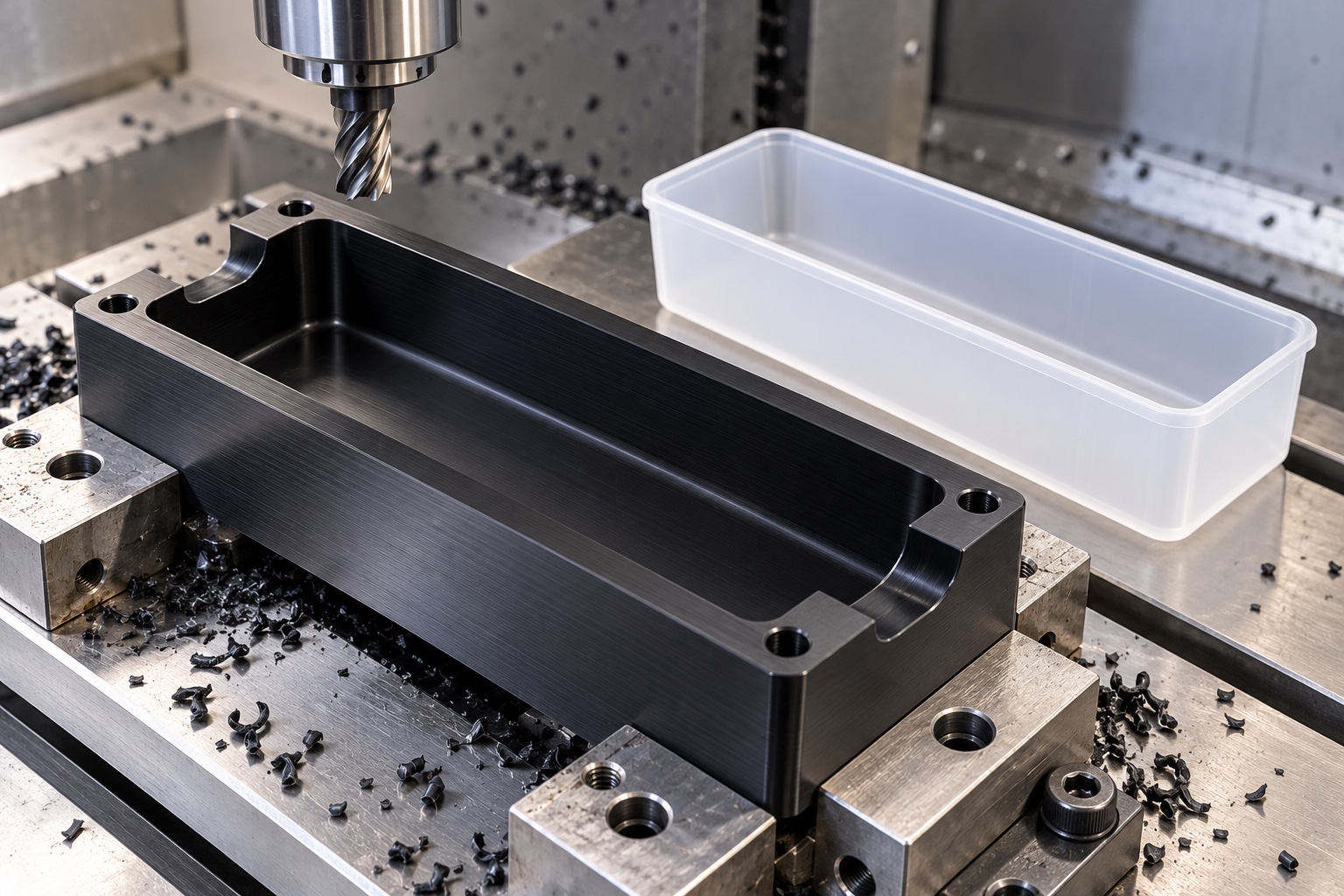
Specify POM grade rather than color
Black POM may be considered for a proposed holder, but color alone does not identify the material or approve its use. State the required grade, raw material form and evidence. Review compatibility with actual cleaning chemicals and environmental conditions using appropriate material information. A non-fluid-contact role does not remove the need for that review, especially where a spill could expose the surface. The supplier should not infer biological suitability or sterility from a polymer designation. Any substitution should be approved before production rather than treated as equivalent because two blanks look equally black.
Plan pocket machining without forcing the walls
A long pocket removes material and can leave walls that respond to workholding pressure. Plan support and operation sequence so the released holder retains the drawing-defined geometry. Avoid clamping across a region that must remain free for inspection. Sharp tools, appropriate access and a controlled finishing allowance help create the specified features, but there is no universal cutting parameter for every POM grade and holder shape. Check the component after releasing the fixture where required. A cavity measured only while forcibly restrained may hide the condition that matters during real assembly.
Resolve internal corners and floor transitions
Rotating cutters leave internal radii that must be compatible with the consumable's outside shape. Define these transitions before production, including any permitted relief that helps seating without reducing necessary support. A smooth-looking pocket is not automatically correct if a corner prevents the reservoir from reaching its intended height. Inspect the entry, lower corners and handling cutouts as functional regions. Edge finishing should remove attached material without changing the approved locating geometry. Uncontrolled scraping to make one container fit can produce an undocumented design that cannot be reproduced reliably on the next order.
Relate the cavity to equipment mounting
The useful seating geometry is its relationship to the holder's installed references. Mounting holes, locating features and support surfaces should share a clear geometric reference scheme. A cavity depth measured from an arbitrary top face may not establish the container height relative to the equipment interface. Include the approved fastener-head and tool access where they affect loading. If a second machining setup is required, preserve reference transfer deliberately. Resolve any disagreement between model and drawing before machining rather than expecting the assembly team to compensate for an ambiguous component after delivery.
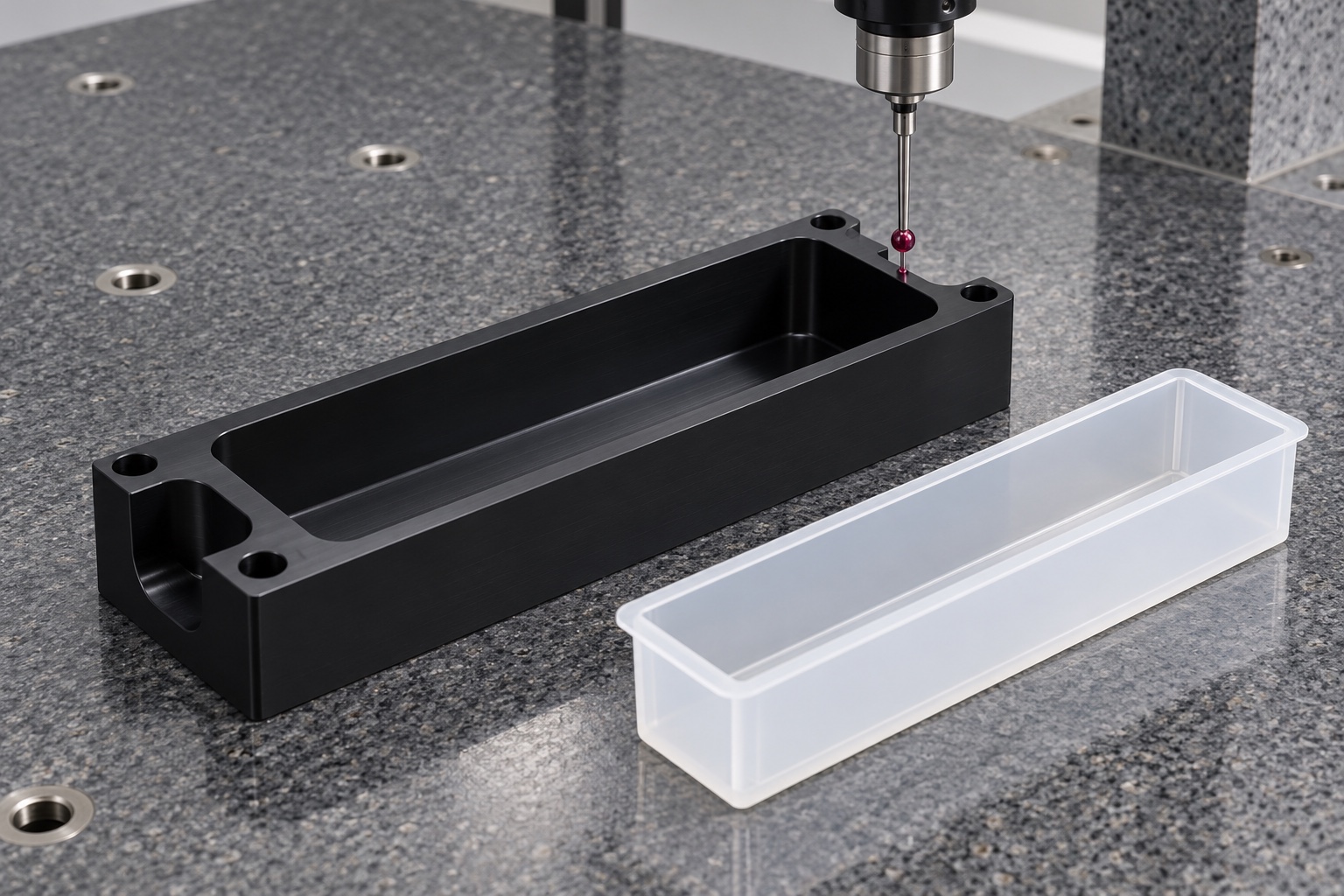
Use a suitable polymer inspection condition
The measurement plan should consider part condition and the contact method used on polymer surfaces. Avoid forces that deform thin walls or obscure the required geometry. Depending on accessibility, optical measurement, coordinate measurement or controlled height checks may address different drawing features. Record the references, support arrangement and any required environmental conditioning. A single pocket-width result does not establish seating height, corner clearance and mounting relationships. Where a feature cannot be verified reliably, agree an appropriate method before production instead of reporting an easier dimension that does not control the actual interface.
Define fit checks without claiming assay results
A controlled trial using identified empty reservoirs can check loading, seating and removal according to an agreed procedure. It cannot establish liquid transfer accuracy, reagent compatibility, sterility or diagnostic performance. Those require separate equipment and application evaluation. Record the holder revision and consumable identity, including any permitted sample variation. If a trial reveals interference, document the actual contact before modifying the pocket. Results from one unrecorded consumable sample should not be extended to every reservoir model or supplier, even if the nominal capacity and general outline appear similar.
Clean and package to a stated scope
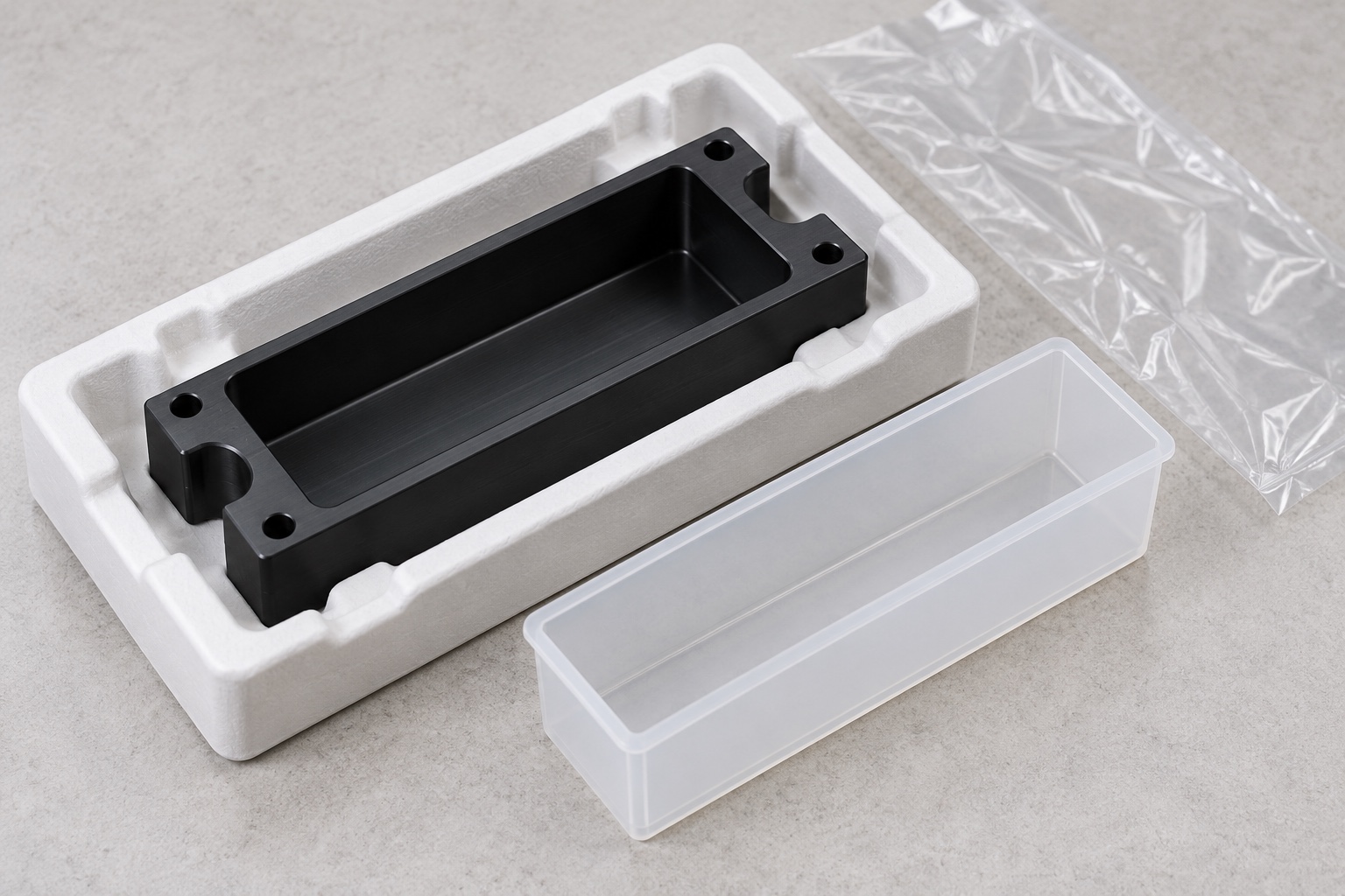
Remove loose machining debris using an agreed process compatible with the documented polymer and assembly requirements. Protect the cavity and locating features from rubbing, fibers and residue during transport. Separate holders so their thin walls and cutout edges do not interlock. Ordinary protective bags are not sterile barriers, and a clean appearance does not establish a quantified cleanliness level. Where a cleanliness criterion is purchased, define its verification method and responsibility explicitly. Maintain material and revision identification with the shipment without adding an unapproved mark to a surface that controls seating or contact.
Make consumable changes visible in repeat orders
The inquiry should include the holder drawing, model, approved consumable geometry, mounting arrangement, POM grade, cleaning requirements and inspection evidence. State whether an empty-container fit trial is included and distinguish it from liquid-handling validation. For repeat production, preserve the approved configuration and authorized changes. A revised consumable flange or bottom shape may require review even when its advertised capacity is unchanged. This creates a practical purchasing boundary: a defined non-fluid-contact support interface with traceable dimensional evidence, without unsupported promises about the laboratory instrument or the assays performed on it.
Manufacturer background reference: lifesciences.tecan.com.
FAQ
Does reservoir capacity define the holder geometry?
No. The approved outside shape, flange, bottom contour, allowed variation and intended contact regions define the interface. Capacity alone cannot establish pocket dimensions or the installed seating height.
Is the holder automatically outside the fluid path?
No automatic assumption is made. Confirm its role in the actual equipment configuration, including relevant exposure requirements. A non-fluid-contact description does not establish cleanliness, sterility or material suitability.
Can all cavity walls be treated as locating surfaces?
Only if the approved design requires that arrangement. Distinguish support, lateral positioning and clearance so the consumable is not forced into unintended contact or deformation during loading.
Why inspect internal corner transitions?
A corner can prevent full seating even when cavity width and length appear correct. Tool radii and approved reliefs must be compatible with the container geometry and verified within the drawing requirements.
Does an empty-reservoir fit trial prove liquid-handling performance?
No. It can check agreed insertion, seating and removal only. Transfer accuracy, reagent compatibility, sterility and diagnostic performance require separate procedures and evidence from the responsible equipment program.
What changes require a renewed review?
Review altered consumable geometry, polymer grade, mounting arrangement, cleaning process or holder design. Preserve approved revisions and test samples so a repeat order does not silently inherit an obsolete interface.

tanghangyun@oemach.com