
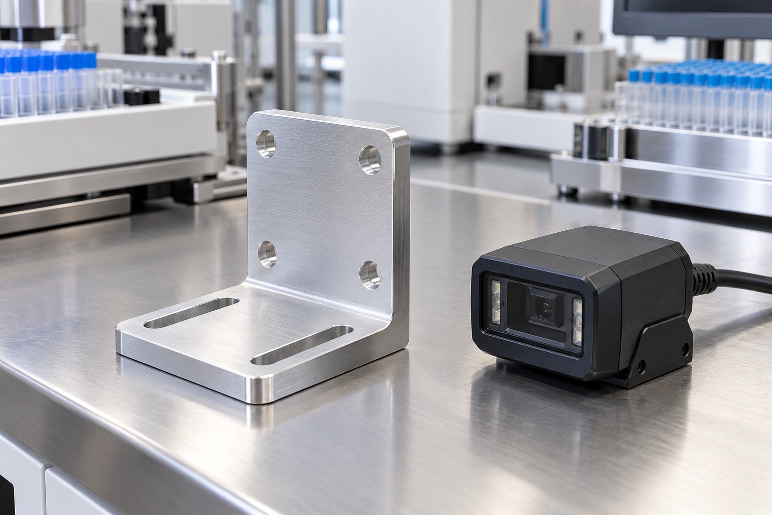
Treat the mount as a mechanical interface
A barcode reader installed in diagnostic equipment needs a controlled relationship to the objects it reads. A machined bracket can establish mounting position and provide adjustment, but it cannot determine reading performance on its own. Optics, lighting, codes, software and the equipment workflow also matter. This article addresses the equipment-side mechanical component rather than patient identification policy or diagnostic validation. Begin with the approved reader configuration and interface drawing. Do not assume a bracket is interchangeable with a commercial accessory because its outline and mounting holes look similar in a photograph.

Obtain configuration-specific reader information
Reader dimensions can vary with lens, connector and body configuration. The referenced manufacturer's dimensional documentation distinguishes several arrangements, illustrating why a supplier needs the correct version rather than a generic box model. Request the approved mounting information from the equipment owner and identify any revision that controls the purchase. Define the accessible mounting faces and keep catalog reference dimensions separate from the custom bracket's acceptance requirements. The drawing must resolve the actual hole relationships, fastener engagement and surrounding clearances before production, rather than leaving those decisions to a sample fitting exercise.
Locate the reader without blocking its view
A bracket should support the reader while keeping the required viewing region and lighting path clear. The equipment team must define that region for the intended code and working arrangement. A hole pattern alone does not show whether the bracket edge, a nearby cover or an adjustment screw enters the view. Review the assembly from the optical direction as well as from the fastening side. Do not transfer a reader manufacturer's performance statement to a different mounting geometry. The machining supplier can verify specified interfaces, while the equipment program evaluates the resulting reading configuration.
Distinguish adjustment from final location
Slots can allow positioning during installation, but their presence does not create a repeatable final reference automatically. Identify what locates the bracket after adjustment and how the approved installation procedure secures it. Specify slot width, end geometry and relevant relationships only where required by the design. Review washer and screw-head contact across the permitted adjustment range. If a fastener bridges a slot poorly, the assembly issue cannot be solved by tightening to an invented torque. The equipment designer must approve the hardware, engagement and final mounting condition as a coherent arrangement.
Include connectors and cable movement
A reader body may fit while its connector or cable cannot be installed or removed. Include the actual approved connector envelope, service access and cable route in the review. The relevant clearance may change when a cover is removed or an adjustable bracket reaches one end of its travel. A mounting supplier should not prescribe a universal bend radius without the cable specification. Keep electrical and communication qualification separate from mechanical clearance checks. The manufacturing drawing should make clear which features are fixed and which positions are established only during the equipment's controlled installation procedure.
Select material and geometry together
6061 aluminum may be suitable for a proposed bracket when the equipment design specifies it, but an alloy name is not a complete stiffness or environmental specification. Upright height, section thickness, internal corner shape and mounting support all influence the component's behavior. Obtain the required material condition and documentation, and identify any finishing process before setting final dimensions. A generous inside radius may help manufacturing but must not collide with the reader body. Conversely, removing material to create a sharper-looking corner is not justified unless the drawing and tool access support that geometry.
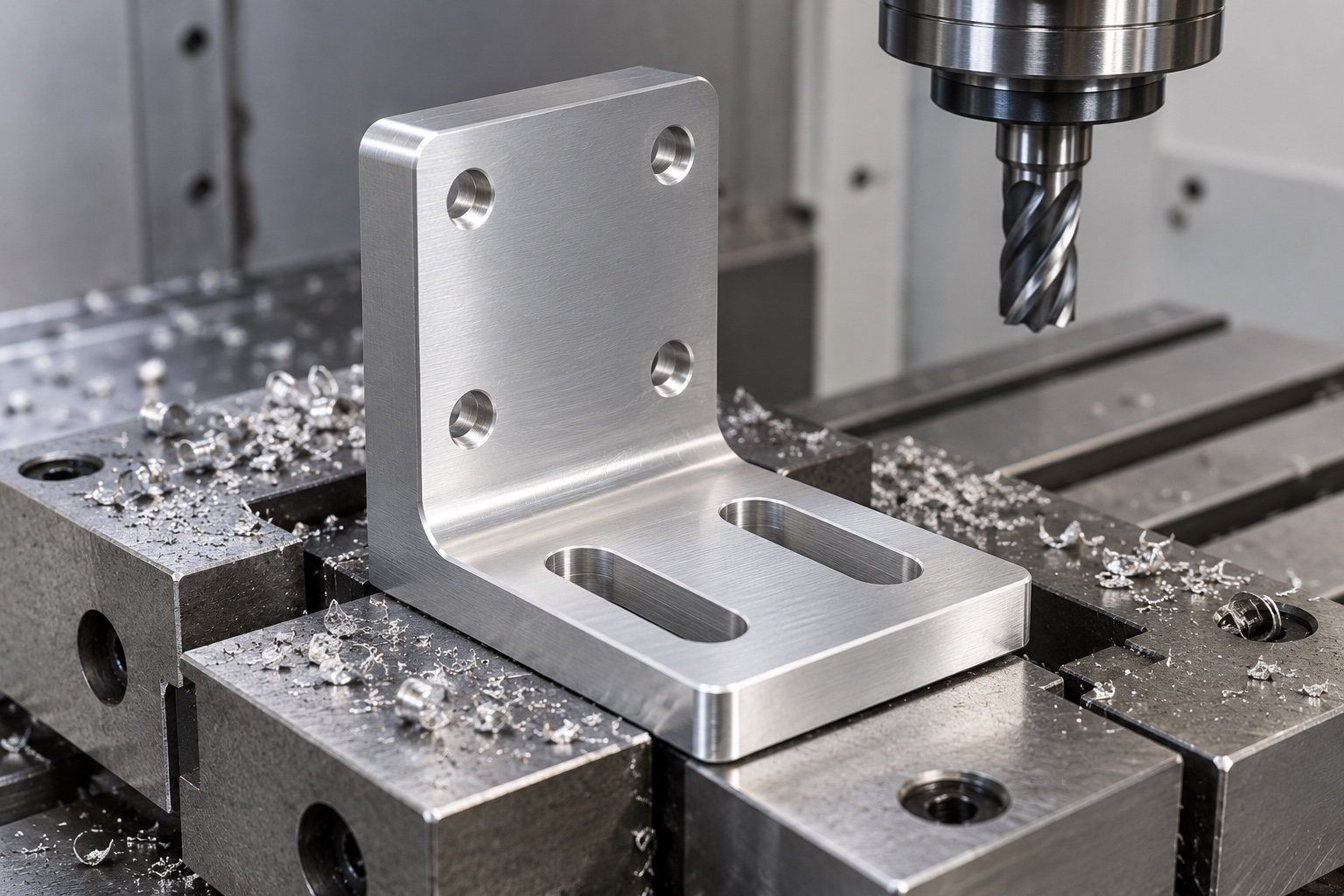
Preserve references through CNC setups
An integral right-angle bracket commonly requires access to more than one face. Establish a manufacturing reference scheme that preserves the relationship between the base and the reader mounting face through those operations. Use support that does not force the upright into a misleading position. Chips beneath setup contacts can introduce an error even when the program is correct. After unclamping, inspect the relevant geometry in the drawing-defined condition. A correct machine coordinate does not replace final verification of the finished bracket, particularly when thin sections or large adjustment slots reduce local stiffness.
Control edges and surface treatment
Burrs around slots and holes can affect screw seating, installation access or cable contact. Specify edge conditions for functional regions instead of relying on unrestricted hand blending. If anodizing is required, identify masking and final-state inspection needs before treatment. Appearance can be documented separately from dimensional acceptance. The article does not prescribe a universal coating thickness or claim compatibility with every cleaning chemical. The approved equipment environment determines material and finish suitability. Keep adhesive labels and unapproved markings away from defined reference contacts and surfaces used to seat the reader or mounting hardware.
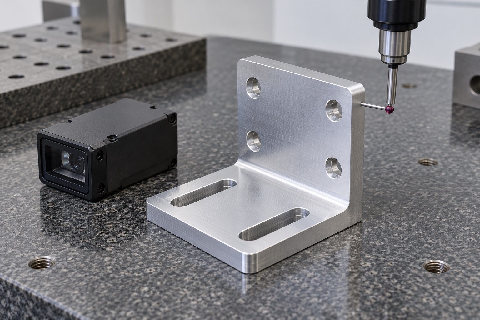
Measure the mounting relationships
The inspection plan should connect each drawing requirement to a suitable method, including the relationship of the mounting face to the base and the positions of specified holes or slots. Record support conditions and inspect without hiding distortion through excessive fixture force. An isolated slot-width result does not establish the final orientation of the reader face. If the design requires measurement under a defined installed condition, state the mounting arrangement separately. A feature-numbered report helps the equipment team distinguish verified component geometry from installation adjustments that must still be completed during assembly.
Define the assembly trial and reading evaluation
An agreed trial can check fastener access, bracket adjustment and cable clearance using identified mating components. Reading evaluation is a different task that needs the equipment team's procedure, code samples, operating conditions and acceptance criteria. Do not describe a mechanical trial as proof of error-free identification. Record the bracket revision, reader configuration and installed position used in any demonstration. If the position changes, the responsible team should review the affected checks. Unrecorded hand fitting may produce a convincing prototype while leaving no controlled basis for manufacturing or qualifying the next unit.
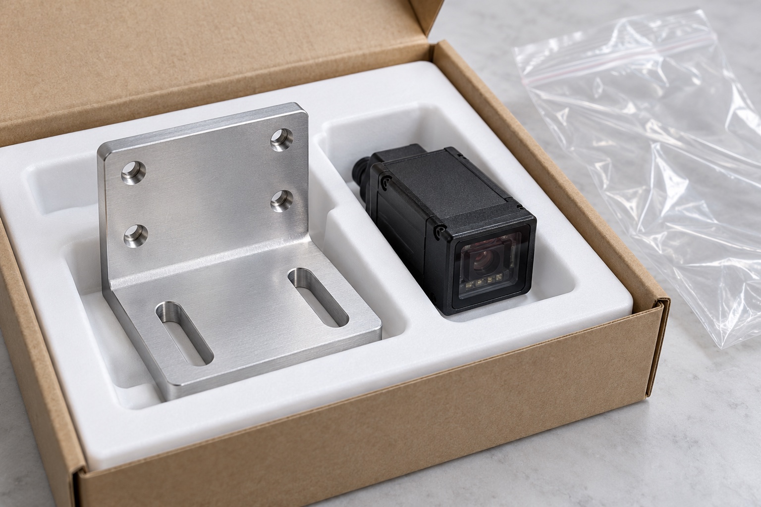
Protect the bracket before installation
Transport packaging should prevent impacts to the upright face, rubbing of reference surfaces and damage to slot edges. Separate brackets rather than allowing them to interlock. Cleaning and packaging requirements should match the agreed assembly process; an ordinary protected component is not a sterile medical product. If a quantitative cleanliness requirement applies, define its evidence independently of a tidy package photograph. Preserve material identity and revision information with the lot. Any supplied installation samples should be identified separately so that the recipient does not mistake an unapproved trial component for an accepted production configuration.
Make repeat orders configuration-specific
A complete inquiry includes the approved bracket drawing, model, reader configuration, hardware, connector envelope, material condition, finish and inspection deliverables. State whether an assembly trial is purchased and who performs the reading evaluation. Retain the approved revision and any authorized prototype changes for repeat production. Changes to a lens arrangement, connector or mounting support should trigger interface review even if the bracket itself seems unchanged. This purchasing boundary supports a verifiable mechanical component without asking a CNC supplier to invent the performance requirements of an entire medical laboratory identification system.
Manufacturer background reference: docs.cognex.com.
FAQ
Does the bracket establish barcode reading performance?
No. It establishes specified mechanical relationships. Reading depends on the approved reader configuration, optics, illumination, code samples and equipment workflow. The responsible team must define and perform the required system-level evaluation.
Why is the exact reader configuration needed?
Dimensions and access can change with lens, connector and body arrangement. Use approved configuration-specific information rather than a generic model or a similar-looking reader when defining mounting and clearance requirements.
Do slots guarantee repeatable installation?
No. Slots permit adjustment. The equipment design and installation procedure must define the final position, hardware contact and securing method, along with any checks required after adjustment.
Can cable clearance be checked from the reader body alone?
No. Include the actual connector, cable route and service access. Any cable bending requirement must come from the approved cable information, not an arbitrary value supplied for a generic bracket.
What should the dimensional report cover?
It should cover the drawing-defined reference scheme, mounting-face relationships and relevant hole or slot geometry. State whether measurements apply in the free condition or a separately defined installed condition.
When must a repeat order be reviewed?
Review changes to reader configuration, hardware, connector, mounting support, material or finishing requirements. Retain authorized prototype changes so production does not reproduce an obsolete or undocumented installation arrangement.

tanghangyun@oemach.com