
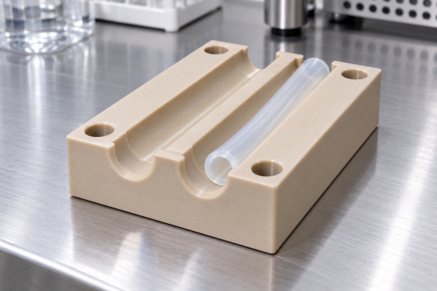
Distinguish the guide from the fluid path
A pinch valve can control a fluid path by compressing flexible tubing from outside. In the designs described by the referenced valve manufacturer, the tubing is the wetted element. A separate machined guide may locate that tube relative to an actuator without contacting the fluid. This article concerns such an equipment-side guide, not a validated valve or a sterile fluid component. The boundary matters: a guide drawing cannot establish tube life, shutoff performance or compatibility with a medical fluid. Those belong to the specified tubing and complete valve assembly.

Start with the actual tubing specification
Tube outside diameter is only one design input. Wall thickness, material, permitted dimensional variation, bending behavior and the approved operating configuration affect the interface. Obtain the actual tubing specification and the valve designer's requirements before choosing a channel profile. A sample length can support discussion but should not replace controlled documentation. Different tubes with a similar outside diameter may behave differently under compression. The machining supplier should not decide a universal channel clearance or substitute a tube merely because it fits inside an open groove on the inspection bench.
Separate guiding from compression
The guide may support entry and exit routing while the actuator supplies a defined compression action elsewhere. Identify these zones on the interface drawing. A channel that unintentionally restrains the tube can change how the assembly behaves, even if its individual dimensions meet a loosely specified model. Leave the necessary clearance for the approved actuator movement and for loading or replacing the tubing. Review the complete motion envelope, not just the closed position. The equipment designer must establish which contacts are intentional and which would create interference or unintended tube loading.
Design channel entrances deliberately
Sharp entrances, abrupt steps and machining burrs can create unwanted contact with a flexible tube. The drawing should define suitable transitions and the areas requiring particular edge inspection. A large radius is not automatically better if it reduces location control or enters an actuator clearance zone. Similarly, a highly polished appearance does not establish an acceptable surface texture. Specify the geometry and surface requirements needed by the approved design. Inspect intersections and exits as well as the most visible channel floor, because hidden transitions may control how tubing is inserted and removed.
Select a documented polymer grade
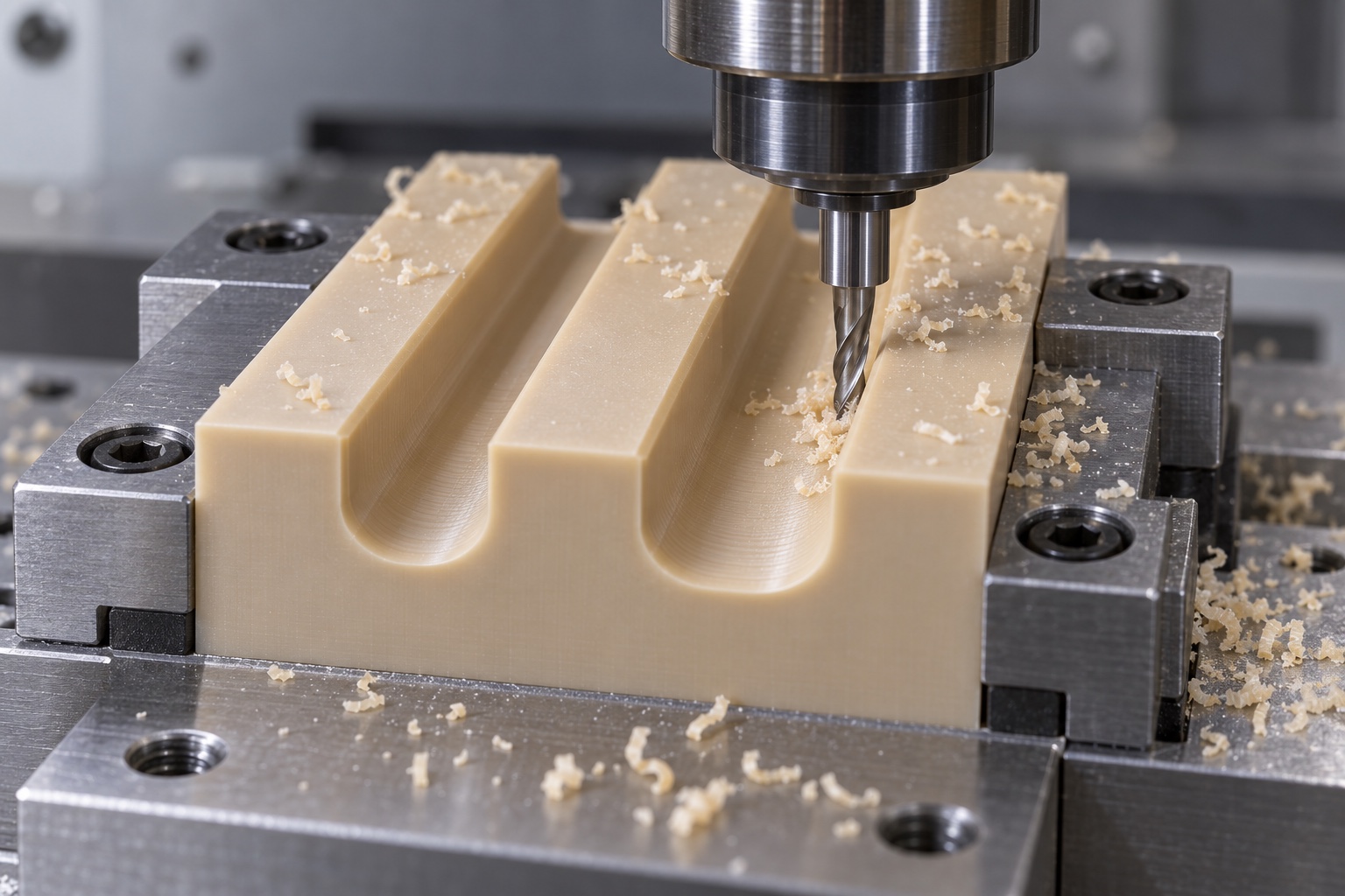
PEEK may be considered for a proposed guide, but the name alone does not approve a material for a specific medical equipment environment. Specify the grade, raw material form and any required documentation. Fillers and processing history can affect machining and the finished surface. Cleaning chemicals, temperature exposure and long-term assembly conditions require application review with appropriate material information. Do not assume that a beige polymer is PEEK or that every PEEK grade is equivalent. Material suitability and any biological or regulatory assessment must remain separate from a supplier's dimensional machining capability.
Use supported polymer workholding
A small polymer block can be deformed by excessive clamping. If machining or inspection occurs while the part is distorted, the released channel may differ from the apparent result. Plan broad support and controlled contact locations that do not obscure critical geometry. Sharp tools and a suitable process help produce defined features, but cutting parameters depend on the chosen grade and setup. Avoid universal recommendations for speed or feed. Check the part after releasing workholding and allow the inspection condition to stabilize as required by the agreed measurement procedure.
Keep channels related to mounting features
The useful channel location is its relationship to the installed actuator and tube route. A groove width measured without references may say little about assembly alignment. Define geometric reference surfaces, mounting-hole relationships and the channel center or profile requirements in the drawing. Where a second machining setup is needed, preserve the reference transfer. Screw-head clearance and tool access should also be reviewed, since fasteners can interfere with tubing even when the polymer component itself is unobstructed. The interface review should include the actual approved hardware rather than an idealized hole pattern.
Remove polymer residues without changing geometry
Polymer machining can leave thin attached material at channel entrances and hole exits. Define an inspection and removal method that preserves the approved profile. Uncontrolled scraping, heating or solvent exposure should not become an undocumented finishing process. If a smooth channel surface is required, identify how it will be evaluated rather than accepting a glossy appearance alone. Remove loose debris before trial assembly so that an apparently successful tube fit does not hide particles at a contact surface. Keep any cleaning process consistent with the documented material and equipment requirements.
Measure under an agreed condition
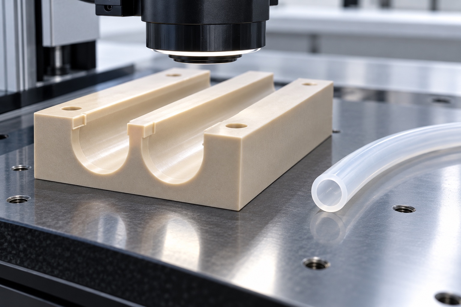
A polymer component's measured size depends on its condition and the method used to contact it. The inspection plan should specify environmental conditioning where required and avoid excessive measurement force on flexible features. Optical measurement can help evaluate accessible profiles without contact, while coordinate or other methods may be suitable for mounting relationships. No one instrument is automatically sufficient for every feature. Record the part revision, measurement references and inspection state. Where a drawing requirement cannot be reached reliably, resolve the method before production rather than substituting an easier but unrelated dimension.
Define tube trials and valve tests separately
A guide trial can check loading access and agreed clearance using the specified tubing. Complete valve evaluation may additionally require an approved procedure for actuator movement, occlusion, leakage, tube condition and repeated operation. The responsible equipment team must define these tests and their acceptance criteria. A guide supplier should not claim that a dimensional report proves shutoff or service life. Record tube identity and assembly revision during any agreed trial. Changing tube material, actuator travel or guide geometry should trigger review rather than inheriting results from a different configuration.
Protect the non-wetted component in transport
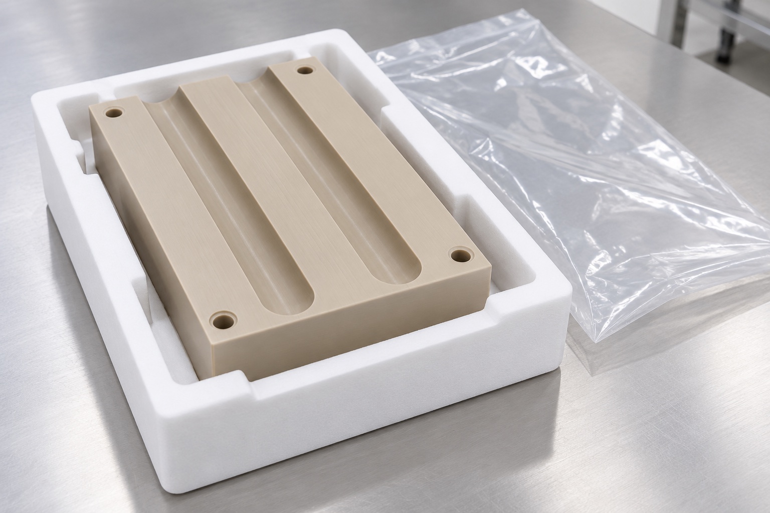
A guide supplied outside the fluid path still needs protection from debris and surface damage. Separate finished blocks to prevent channel edges rubbing against neighboring parts. Choose packaging that does not leave residues or fibers in functional areas under the agreed cleanliness requirement. Ordinary protective packaging is not sterile packaging, and a non-wetted description is not a claim of cleanliness or suitability for every medical application. Keep lot identity and material documentation associated with the shipment. If clean assembly is required, its acceptance method and responsibility should be stated explicitly in the purchase scope.
Make the purchase request testable
Provide the approved component drawing, model, polymer grade, tube specification, actuator interface, mounting hardware and required quantities. State which inspection records are needed and whether a separate assembly trial is requested. Clarify any cleaning or packaging acceptance requirements before the supplier selects a process. A useful cost estimate distinguishes machining from material evidence and functional evaluation. For repeat production, preserve approved revisions and review changes to tubing or cleaning procedures. This makes the guide a controlled mechanical interface instead of an undocumented component expected to guarantee the performance of an entire medical fluid-control system.
Manufacturer background reference: www.takasago-fluidics.com.
FAQ
Does non-wetted mean the guide is sterile?
No. It describes the intended separation from the fluid path in the specified assembly. Cleanliness, sterility and application suitability require their own requirements and evidence; they do not follow from that label.
Can channel clearance be selected from tube diameter alone?
No. Use the actual tube specification, variation, routing and actuator interface. The equipment designer must approve the clearance and contact arrangement for the complete configuration rather than relying on a nominal diameter.
Is every PEEK grade interchangeable?
No. Specify the approved grade, raw material form and documentation. A grade or supplier change should be reviewed for machining, surface condition and the actual equipment environment before being treated as equivalent.
Why inspect the guide after unclamping?
Workholding can distort polymer geometry. Released-condition inspection helps establish the actual component shape. The drawing may also require a separately defined installed condition, which must not be confused with the free condition.
Does a dimensional report prove tube shutoff?
No. Occlusion, leakage and tube life are assembly-level questions involving tubing, actuator and guide. They need an approved test procedure and acceptance criteria beyond the machined component's dimensional report.
Which changes require renewed interface review?
Changes to tube specification, guide geometry, polymer grade, actuator movement or mounting arrangement should be reviewed. Cleaning and packaging changes may also matter when they affect the agreed component acceptance requirements.

tanghangyun@oemach.com