
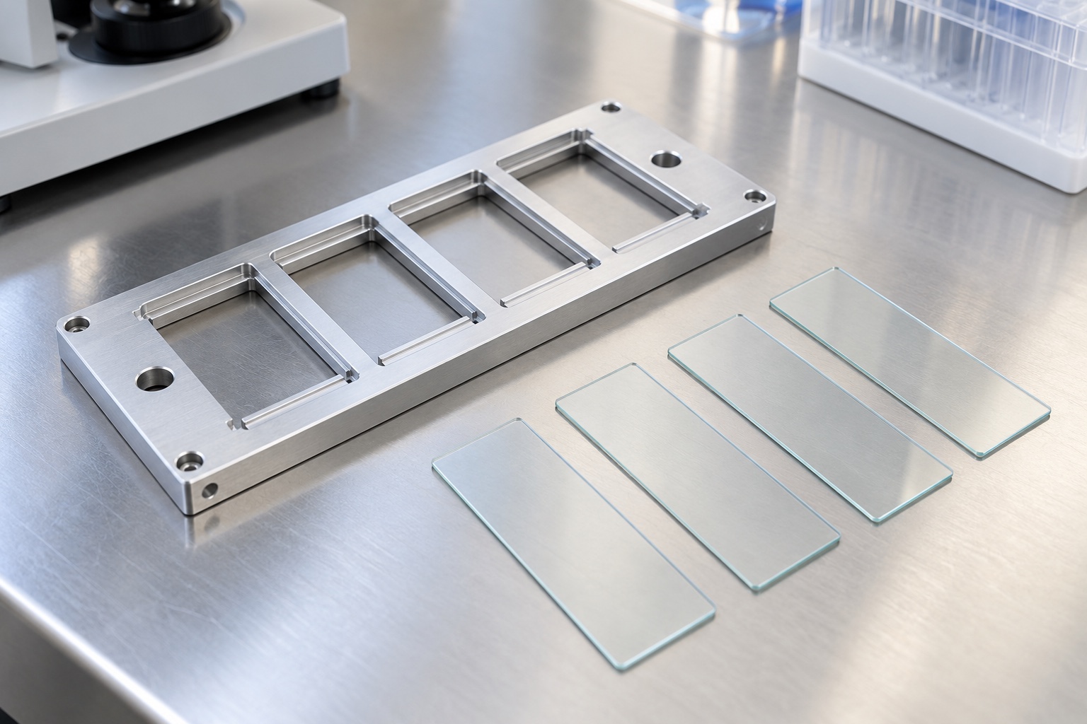
Define the carrier boundary
A digital slide scanner carrier is an equipment-side mechanical interface. It supports glass slides, presents them to the handling mechanism and leaves the specified imaging area accessible. It is not an optical calibration standard or evidence of diagnostic performance. Before requesting a machined part, distinguish a removable carrier from the scanner rack, transport mechanism and slide itself. Manufacturer documentation shows that compatible slide dimensions and loading arrangements are product-specific. A custom carrier therefore needs its own approved engineering drawing and assembly review; resemblance to a commercial accessory does not establish interchangeability.

Separate support from positioning
A support ledge establishes where the glass rests, while locating surfaces constrain lateral movement. A retaining feature may prevent lift without defining the primary position. These roles should be shown separately on the drawing. If every wall is treated as a tight locating surface, normal variation in glass size can create an overconstrained assembly. If a hold-down touches the wrong region, it can tilt the slide rather than seat it. Review the loading direction, the accessible glass edges and the intended contact sequence with the equipment designer before assigning manufacturing tolerances.
Obtain the full glass envelope
A nominal slide length and width are not enough to design a carrier. The interface review should include permitted thickness, edge condition, labels, coverslip position and any allowed overhang. These details belong to the actual scanner and specimen preparation workflow, not a universal machining rule. Show which zones may contact the carrier and which must remain clear. Use clean blank surrogate slides for early mechanical fit checks. Do not use biological specimens in a general machining inspection area, and do not infer approved sample handling from an unloaded fit demonstration.
Protect the viewing window
The through-window must provide the required optical and mechanical clearance without unnecessarily weakening the frame. Its outline should be related to the approved imaging envelope and the movement of nearby mechanisms. Internal corner radii need agreement because a rotating cutter cannot produce an arbitrarily sharp inside corner. A decorative chamfer must not reduce the glass support width or intrude into the viewing area. Review the underside as carefully as the top: ribs, fasteners and protective pads can become obstructions even when the top opening appears generous.

Choose accessible geometric references
The carrier needs geometric reference surfaces that remain identifiable during machining, finishing and inspection. A practical scheme may reference the mounting plane and defined locating features rather than a convenient outside edge. The drawing should identify how support height, window location and mounting holes relate to those references. Inspection must reproduce the intended support condition without forcing a warped frame flat. Where the assembly clamps the carrier, specify whether a particular requirement applies in the free condition or under a defined mounting condition. These are different acceptance conditions and should not be silently exchanged.
Machine a thin frame without hiding distortion
Large windows remove stiffness from a small aluminum frame. Plan roughing and finishing so that workholding remains supported as material is removed. A fixture that bends the carrier can produce an apparently correct surface while clamped and an unacceptable shape after release. Leave suitable material for finishing, review the sequence between opposite faces and inspect after unclamping. The appropriate cutting conditions depend on raw material, geometry, tools and the machine. No single feed, speed or clamp force can be responsibly prescribed for every carrier from a general article.
Control ledges, corners and burrs
The glass support is a functional contact surface, not merely the bottom of a pocket. Tool access, cutter corner shape and edge finishing must preserve its width and elevation. Small burrs around windows or mounting holes can change seating or scratch glass during loading. Define the required edge condition instead of relying on an unrestricted instruction to polish everything. Examine channel intersections and the underside of through-features under suitable lighting. Remove loose particles without rounding a locating edge that the drawing expects to remain geometrically defined.
Include finishing in the dimension plan
If anodizing or another surface treatment is specified, identify the final measurement condition, masking needs and the surfaces whose dimensions remain critical afterward. A treatment choice must consider the actual equipment environment and cleaning procedure; the fact that aluminum is common in machinery does not prove compatibility with every disinfectant. Do not transfer a supplier's coating claim to the assembled scanner. Coordinate any appearance requirement with the functional surfaces. A visually uniform finish is useful, but it does not replace verification of support geometry, window clearance or locating relationships.
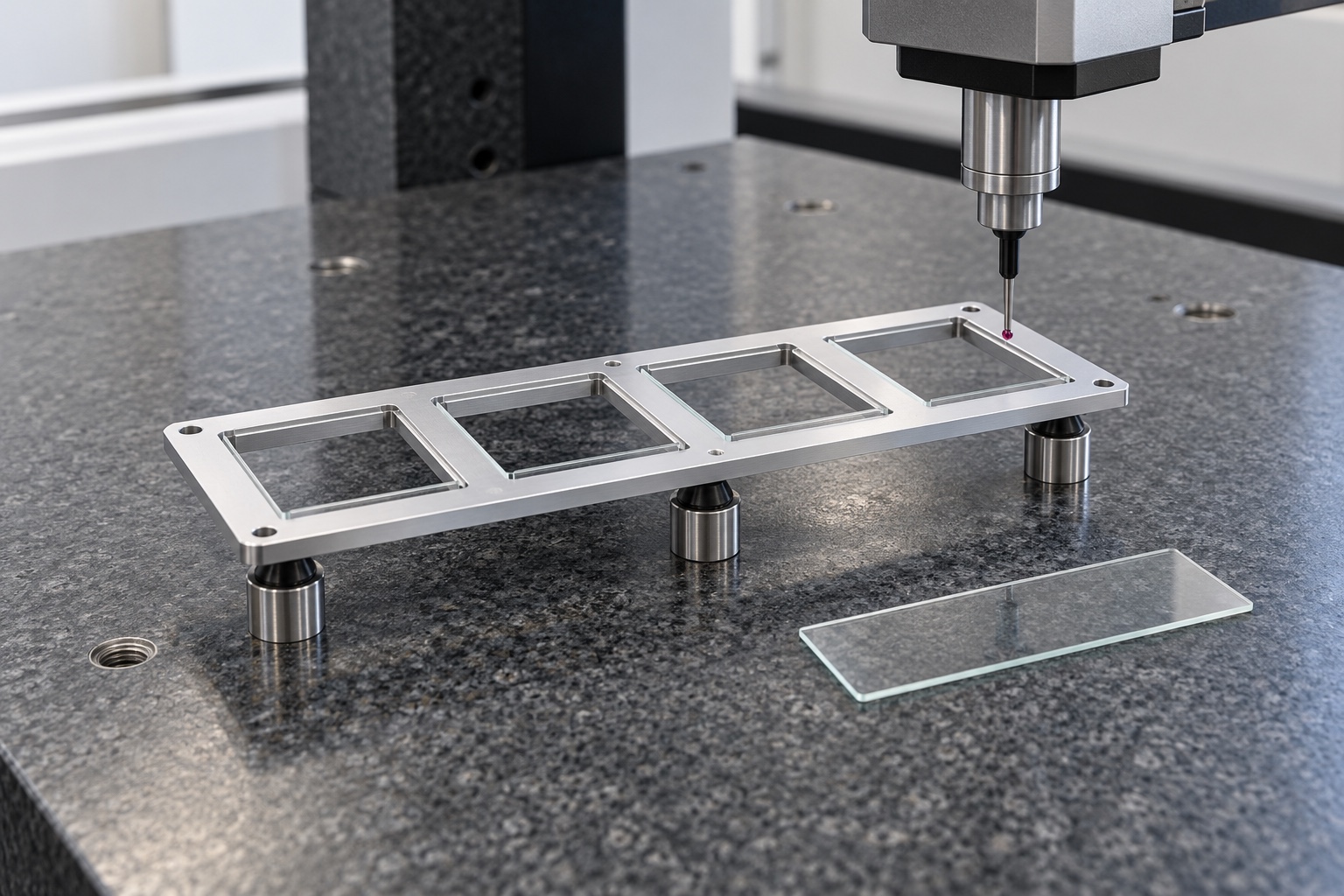
Measure what controls seating
An inspection plan should map each drawing requirement to an accessible measurement method. Depending on the feature, this might involve coordinate measurement, optical measurement or a controlled height comparison. Record the support arrangement, part temperature condition and whether the carrier was unclamped. Flatness of one face does not automatically establish the relative height of several separated support ledges. Likewise, a hole diameter alone does not establish its location relative to the glass seating surfaces. A feature-numbered report makes the acceptance decision traceable to the drawing rather than to an attractive photograph.
Define assembly trials separately
A trial with approved surrogate glass can check loading access, seating and removal under an agreed procedure. It cannot by itself prove focus stability, image quality, slide transport reliability or diagnostic suitability. Those require equipment-level evaluation with appropriate responsibilities and acceptance criteria. Record which carrier revision, mating mechanism and surrogate slide set were used. If a trial exposes interference, document the relevant contact location before changing the design. Unrecorded hand fitting can make a prototype seem successful while leaving no repeatable basis for producing the next carrier.
Preserve the finished interface
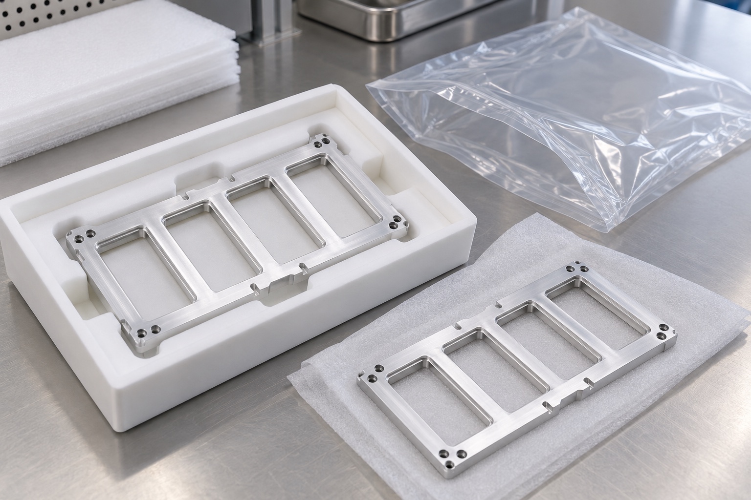
Cleaning and packaging should prevent chips, abrasive contact and uncontrolled pressure on the thin frame. Separate carriers so that support ledges do not rub against neighboring parts. Protect defined locating surfaces without adhesive residue in contact zones. Packaging supplied for transport is not automatically sterile packaging, and an ordinary cleaned component should not be represented as a sterile medical product. Any cleanliness acceptance requirement must be agreed in measurable terms with the equipment owner. Retain identification outside sensitive contact surfaces where possible and keep the drawing revision associated with each shipment.
Prepare a repeatable manufacturing request
A useful request includes the approved drawing, three-dimensional model, glass envelope, mating-interface information, material condition, finish specification, required quantities and inspection deliverables. Identify any customer-supplied surrogate slides and who authorizes their use. Separate the dimensional report from an optional assembly trial and from scanner-level qualification. For repeat production orders, retain the approved revision and any documented changes to raw material, workholding, finishing or measurement. This creates a clear purchasing boundary: a verified machined carrier interface, without unsupported promises about the performance of the complete medical imaging system.
Manufacturer background reference: nanozoomer.hamamatsu.com.
FAQ
Does a standard slide size define the whole carrier?
No. Thickness, labels, coverslip envelope, contact zones and scanner handling geometry also matter. Use the actual equipment requirements and approved interface drawing rather than treating one nominal glass size as a complete specification.
Which surfaces should touch the glass?
Only the support and locating surfaces defined by the approved design. The drawing should distinguish vertical support, lateral positioning and retention, and identify areas that must remain clear during loading and imaging.
Why inspect after removing the clamps?
A thin windowed frame may change shape when workholding is released. Free-condition inspection reveals geometry that can be hidden by clamping; a separately specified mounted-condition check may also be required.
Can the support edges be heavily polished?
Not without design approval. Uncontrolled polishing can alter ledge width, support height or locating geometry. Specify the required edge condition and use inspection that confirms those functional features remain intact.
Does a mechanical fit test prove imaging performance?
No. It can demonstrate agreed loading and seating checks using identified surrogate glass. Focus, image quality, transport reliability and diagnostic suitability require separate equipment-level evaluation.
What should accompany a repeat order?
Provide the approved revision, material and finishing requirements, inspection plan and any authorized interface samples. Include documented prototype changes so the supplier does not reproduce an obsolete or hand-fitted configuration.

tanghangyun@oemach.com