
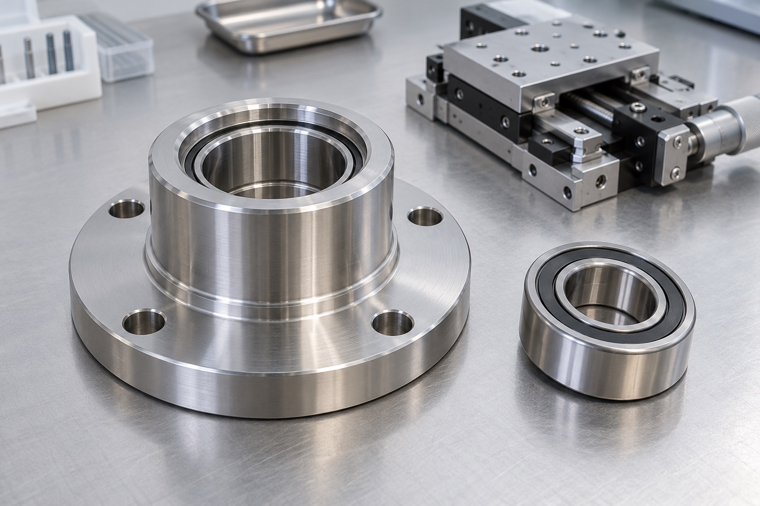
Define the cartridge's place in the stage
A laboratory positioning axis may use a machined cartridge to locate a bearing within a larger frame. The cartridge provides mounting and seating interfaces; the bearing, shaft, retention hardware, actuator and control system complete the arrangement. This guide concerns the equipment-side machined component, not a patient-contact bearing or a validated medical device. Identify whether the cartridge is fixed, adjustable or replaceable and how it is installed. An accurate-looking cylindrical part cannot establish stage accuracy by itself. The drawing must connect the cartridge's measurable features to the actual assembly requirements.

Obtain the bearing arrangement before choosing a fit
The required housing fit depends on the actual bearing and application. Ask for the released bearing reference, loads, arrangement and mounting concept rather than assigning a familiar fit class by habit. The equipment designer determines whether a bearing is intended to locate axially, permit movement or work within a preloaded arrangement. Those choices influence the interface requirements. A machining supplier should reproduce the specified fit and report the agreed evidence, not infer a complete bearing design from an outside diameter. Clarify any incomplete fit notation before tooling or inspection methods are committed.
Separate diameter from geometric relationships
A seat diameter describes size, but the cartridge may also need controls on form, location and its relationship to the axial abutment and mounting interface. SKF's bearing-interface guidance distinguishes dimensional fit from the geometric accuracy of seats and abutments. That principle is useful, but a catalog's general guidance is not a substitute for this cartridge's released tolerances. State the required characteristics using the drawing's chosen system. A two-point bore reading alone does not establish the complete form of the seat or the alignment of a shoulder that locates the bearing axially.
Choose accessible datums and a transfer strategy
The mounting flange and an appropriate locating feature can provide useful references, depending on how the cartridge is installed. The designer must define the actual datum scheme. Plan how those references are created and recovered if turning, boring and mounting-hole operations use different setups. A concentric fixture does not automatically establish every relationship called out on the finished part. Record which surface locates the workpiece, how it is supported and what is measured after the transfer. Avoid using a cosmetic outside diameter as an unapproved substitute for the functional installation reference.
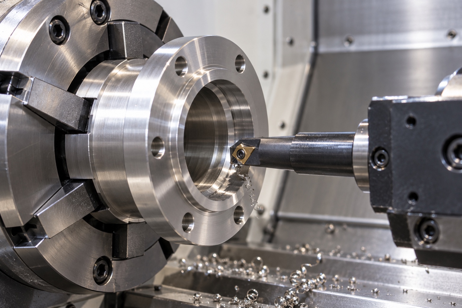
Review the abutment and corner clearance
A bearing ring must reach the intended support region without unintended contact at a corner or relief. Compare the cartridge's shoulder and fillet geometry with the approved bearing interface. Include the required axial position, usable support width and any released relief. Do not simply make the internal corner as small as the available tool permits. A local change can affect support or create an edge that is difficult to inspect. Where access is limited, identify an inspection approach before machining. A correct bore size cannot compensate for a bearing that stops on the wrong feature.
Manage workholding and wall stiffness
A thin cartridge can change shape under a chuck, collet or measurement fixture. Review the available wall section, flange geometry and length of unsupported material through the proposed route. Select support that allows machining without hiding released-state movement. Establish when the part is unclamped and checked, and identify whether the drawing also requires a specified mounted condition. Those are different observations. A bore corrected while the cartridge is distorted may not be correct after release. Keep setup changes traceable so a later dimensional investigation can distinguish tool wear from a change in support or clamping.
Plan the cutting route around the functional axis
One possible strategy establishes a locating diameter and flange face, then finishes the bearing seat and abutment from a controlled axis. The suitable sequence depends on geometry, access and the material condition. Review boring-bar reach, chip evacuation and the effect of finishing one feature on another. If mounting holes need a secondary operation, transfer the agreed references rather than relying only on a machine program origin. The goal is not to prescribe one universal route, but to identify where the process creates and preserves the relationships that the completed cartridge must demonstrate.
Include edge finishing and final treatment
Seat entries, mounting holes and retention features can require different edge conditions. Remove attached burrs without altering the usable seat length or the bearing's axial support. Review the part after any specified surface treatment or cleaning step that can affect acceptance. A treatment certificate does not establish the finished bore size, and a bright surface does not prove that the shoulder is correctly located. Define which dimensions apply after treatment and how the lot is identified. Do not assume a coating or chemical process is acceptable for every bearing arrangement or every laboratory cleaning environment.
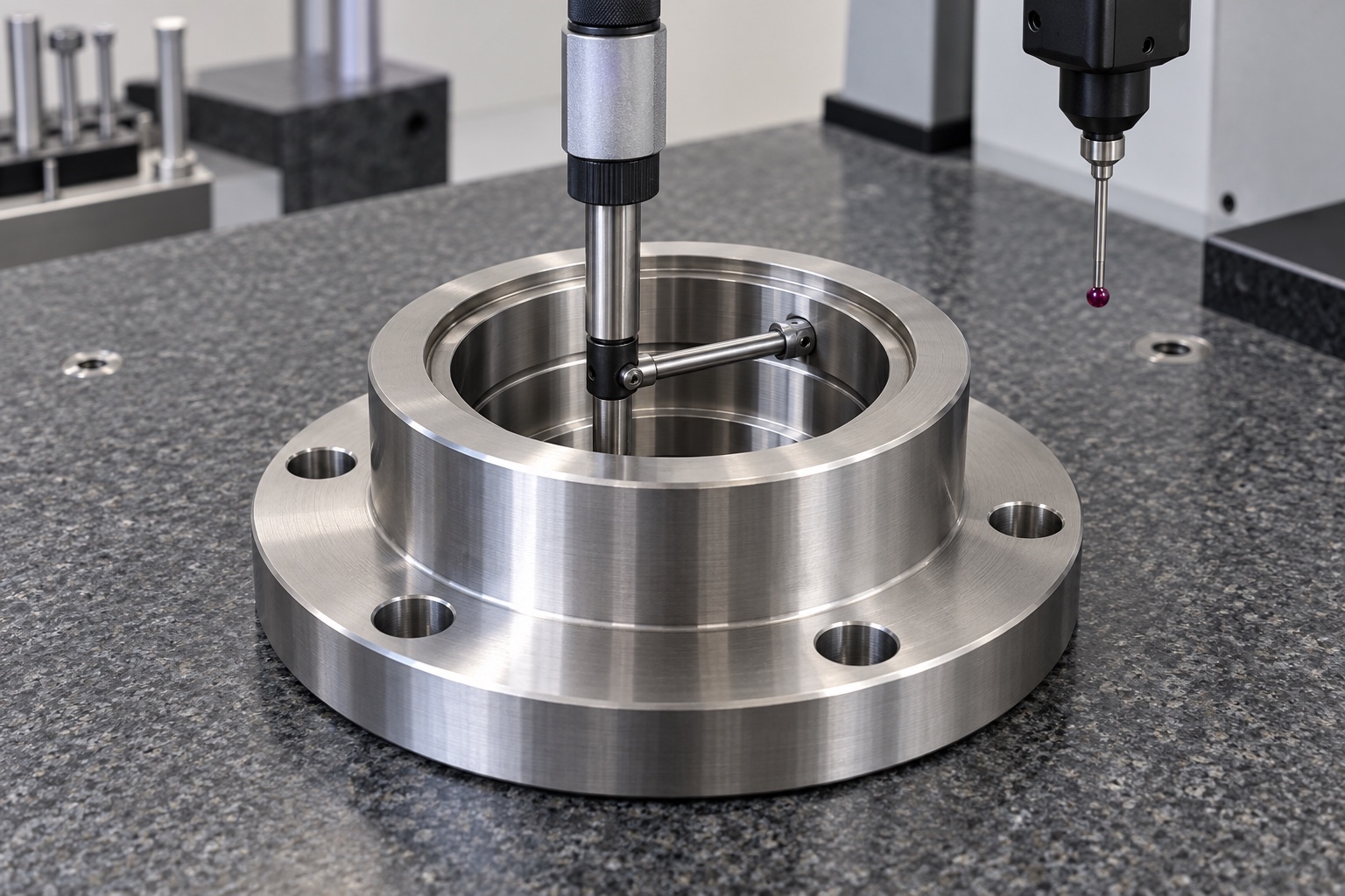
Measure the drawing characteristics with suitable methods
The first-article plan can include material identity, seat diameter, the specified form and location characteristics, abutment geometry, flange features and mounting holes. Choose methods appropriate to bore access and required resolution. Record support conditions, instrument identity and the drawing characteristic linked to each result. Distinguish a direct reading from a calculated relationship. Where a method cannot establish the specified characteristic, resolve the limitation before recording it as accepted. Preserve the finished-condition and free-state results requested by the order rather than replacing them with an informal observation that a bearing can be inserted.
Keep preload and running trials separate
Preload, rotating torque, temperature rise and positioning performance depend on the complete assembly, not only the cartridge. A component drawing may define interfaces used by that assembly without providing a complete trial procedure. If testing is requested, agree the actual bearings, shaft, retention hardware, mounting conditions and observations. Define who assembles and approves the result. A dimensional pass does not prove a preload value, while a bearing that turns by hand does not establish running accuracy. Avoid inventing universal tightening or fit recommendations to fill gaps in the equipment team's requirements.
Protect the seat through delivery
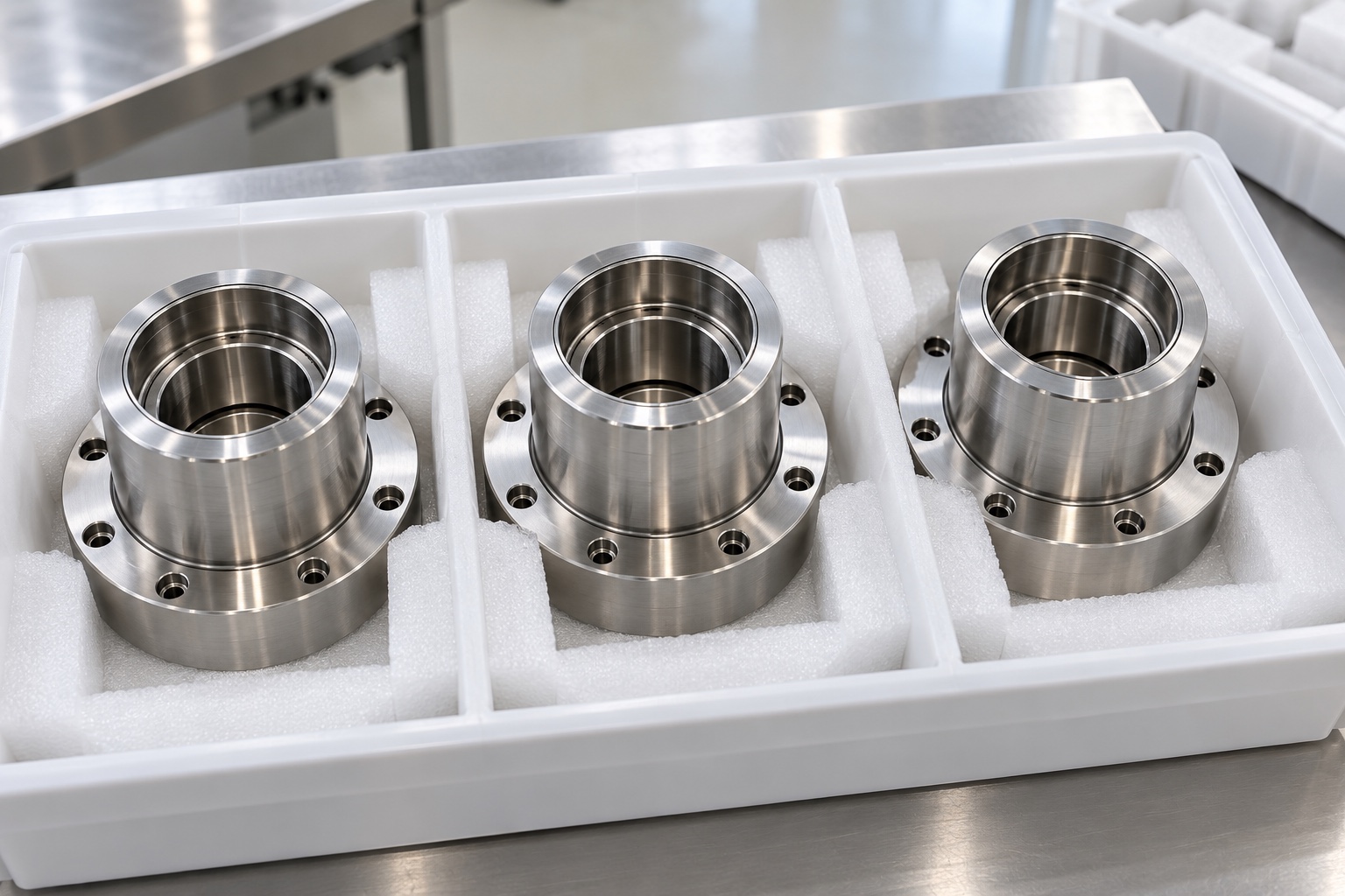
Remove the agreed residues from the seat, shoulder and adjacent passages using a compatible process. Keep abrasive debris, labels and uncontrolled metal contact away from the finished bearing interface. Any protective cap or separator should not damage the entry or introduce material into the bore. Identify the part, revision, quantity and lot on the packaging. Describe the actual cleaning and inspection performed without implying sterility or an unverified cleanliness class. Receiving personnel should be able to find the inspection record and recognize the protected functional region before opening or handling the component.
Make the RFQ specific enough to repeat
Send the controlled drawing and model, exact material condition, bearing reference, fit and geometry requirements, finish, quantities and inspection expectations. Provide approved mating parts only where an agreed trial needs them. List component measurements separately from assembled tests and identify the evidence expected for each. Preserve the accepted first article, authorized deviations and process references for repeat orders. A change to the bearing, flange mounting, material or surface process can justify a review even if the cartridge outline is unchanged. The best repeat order describes the accepted configuration rather than asking for another part that merely looks the same.
Manufacturer background reference: www.skf.com.
FAQ
Who chooses the housing fit?
The equipment design team should specify the fit using the actual bearing arrangement and operating requirements. The machining supplier reviews manufacturability and inspection, but should not substitute a familiar fit class for an incomplete design requirement.
Why is bore diameter not enough?
Size does not establish every form, alignment or abutment relationship. The drawing may require additional geometric characteristics. The inspection plan must address those individually rather than treating one bore reading as proof of complete bearing-seat acceptance.
What determines corner clearance?
Use the approved bearing interface and the released cartridge geometry to define the shoulder, usable support and corner or relief. Do not assume the smallest available tool radius is automatically the correct design.
Can preload be inferred from the housing drawing?
Not reliably without the complete bearing arrangement and assembly requirements. Preload and running behavior depend on other components and procedures. Any requested trial needs a separately agreed configuration, method and acceptance criterion.
In what condition should the part be measured?
Follow the drawing and agreed inspection plan. Released-state measurement and a specified mounted-condition check can provide different evidence. Record support and clamping so the accepted result is not dependent on an undocumented fixture load.
What evidence should accompany delivery?
As ordered, provide material identity, the drawing revision, the agreed dimensional and geometric report, treatment documentation and lot identification. Keep any assembly-trial record separate and describe the actual cleaning and protective packaging supplied.

tanghangyun@oemach.com