
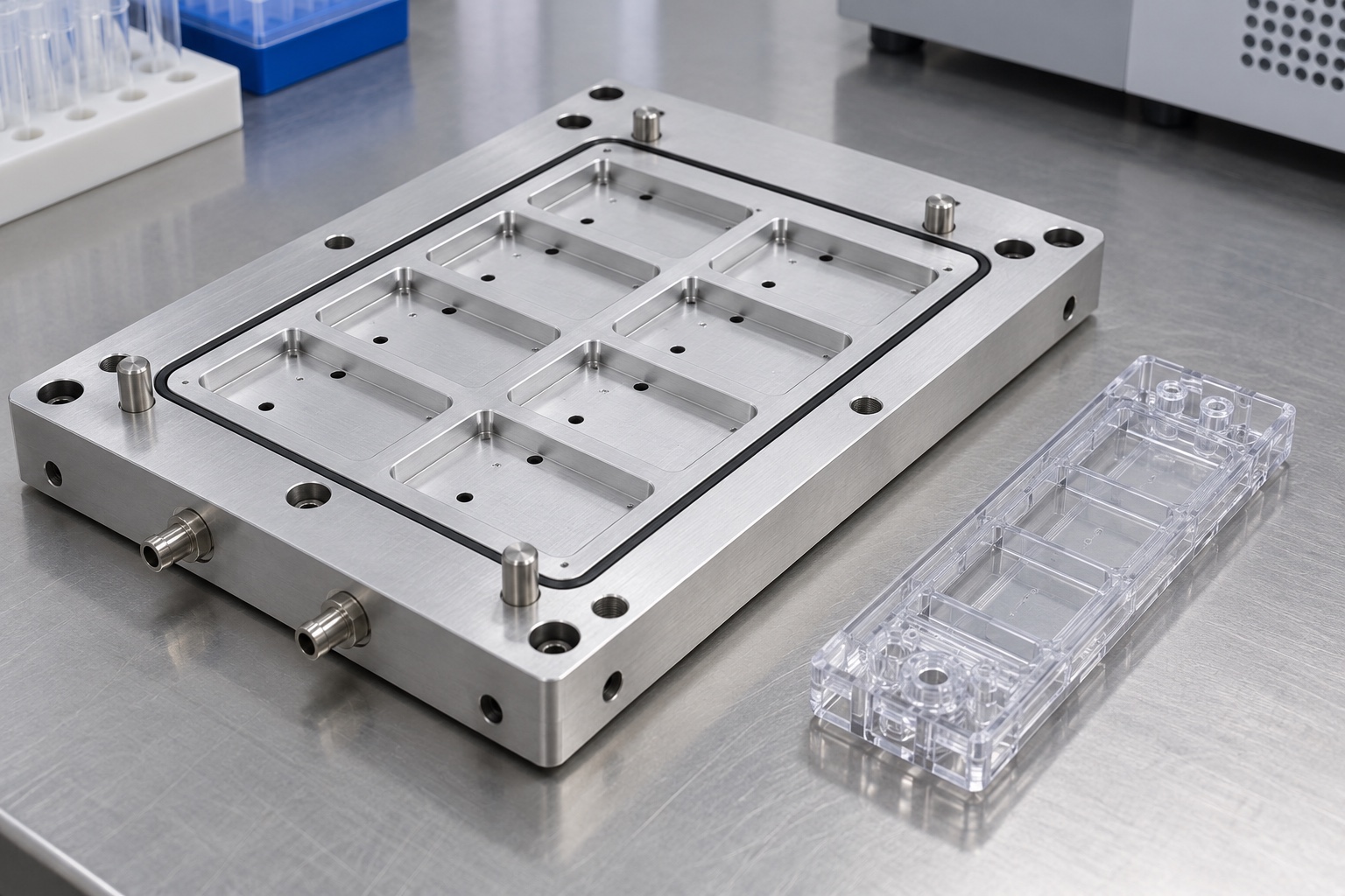
Define the fixture, not the whole instrument
A diagnostic cartridge can need a repeatable position while an inspection station reads a code, checks an assembly or observes a window. A vacuum platen is one possible fixture interface, not a universal solution for every cartridge. This guide concerns equipment-side workholding. It does not describe a patient suction circuit or validate an assay. Before machining, establish the permitted support regions, the orientation of the cartridge and the actions performed while it is held. The equipment team must decide whether the cartridge can tolerate the intended loading without distortion, damage or interference with an optical path.

Separate locating, supporting and sealing features
A pin or edge stop can locate the cartridge laterally, support pads can establish its height, and a gasket can close the evacuated region. Those functions should be identifiable on the drawing. Treating the whole upper face as one undifferentiated precision surface can obscure the real acceptance requirements. Show where the cartridge may touch, where it must remain clear and which surfaces support the seal. Locate the vacuum passage relative to those features. The shop then has a basis for planning inspection and protecting the important regions during deburring, finishing and packaging.
Review the vacuum interface with the mating cartridge
Schmalz explains that vacuum workholding depends on an effective evacuated area and a sufficiently tight interface. That general principle does not establish a holding force for a diagnostic fixture. The cartridge shape, leakage paths, support arrangement and complete vacuum circuit still need review. Obtain approved mating geometry and representative samples if assembly trials are included. Identify which cartridge openings are intentional and whether any would connect the fixture to an unintended volume. A shallow groove that looks continuous in a model may still be interrupted by a port, recess or change in the actual mating surface.
Choose datums that survive manufacturing
Define the mounting interface and the cartridge support system before deciding how the plate will be held on the machine. A practical drawing can relate support height, locating holes and the seal path to accessible reference features. The final datum scheme belongs to the designer; it should not be invented during inspection. Explain whether a flatness requirement applies to individual pads, a collective support region or a continuous surface. Also state whether measurement is made in the free state or under a specified mounting condition. These alternatives can produce different observations on a thin or relieved plate.
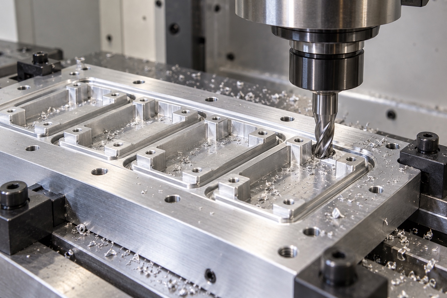
Control material removal and clamping
A plate may appear flat while it is forced against a fixture and change shape after release. Review blank condition, stock allowance, pocket distribution and the sequence used to remove material from each side. Support and clamping should allow finishing without unnecessarily loading narrow webs or sealing lands. An intermediate released-state check can identify movement before the final pass, although the required route depends on the actual geometry and material. Record the setup references that transfer between operations. A cosmetic skim of one surface is not automatically a correction for an incorrectly located support system.
Make seal grooves inspectable
The groove specification should identify width, depth, corner transitions, location and any surface or edge requirements needed by the selected seal design. Do not assign dimensions from an unrelated seal catalog without checking the actual gasket and mating part. Tool access matters at internal corners and close to locating holes. Where a cutter radius prevents the modeled corner, agree the geometry before machining instead of creating an unrecorded relief. Include a method for checking the groove after finishing. A single depth reading cannot establish the complete profile or prove that the assembled seal will operate correctly.
Plan ports, intersections and edge control
Vacuum ports and connecting passages introduce burr and residue risks at their intersections. Review the entire passage, not only the visible opening. Establish which features can be reached directly and which need an agreed indirect check. Remove loose edges without widening a sealing feature or damaging a locating shoulder. A port cleaning operation does not by itself demonstrate that an attached burr has been removed. Keep a record of any plugs, fittings or threaded features included in the delivered configuration, since those can change both assembly access and the boundary of a later leakage test.
Include finishing in the dimensional plan
If anodizing or another finish is specified, identify the treated and masked regions and define which dimensions apply in the finished condition. Consider mounting holes, dowel interfaces, gasket grooves and support pads together. Do not assume that a finish is acceptable merely because its appearance is uniform. Residue or handling damage can affect a groove even when overall plate dimensions remain within drawing limits. A supplier should quote the agreed finish and its documentation rather than imply general compatibility with every laboratory cleaning agent. Any chemical exposure requirement needs the actual material, finish and operating conditions.
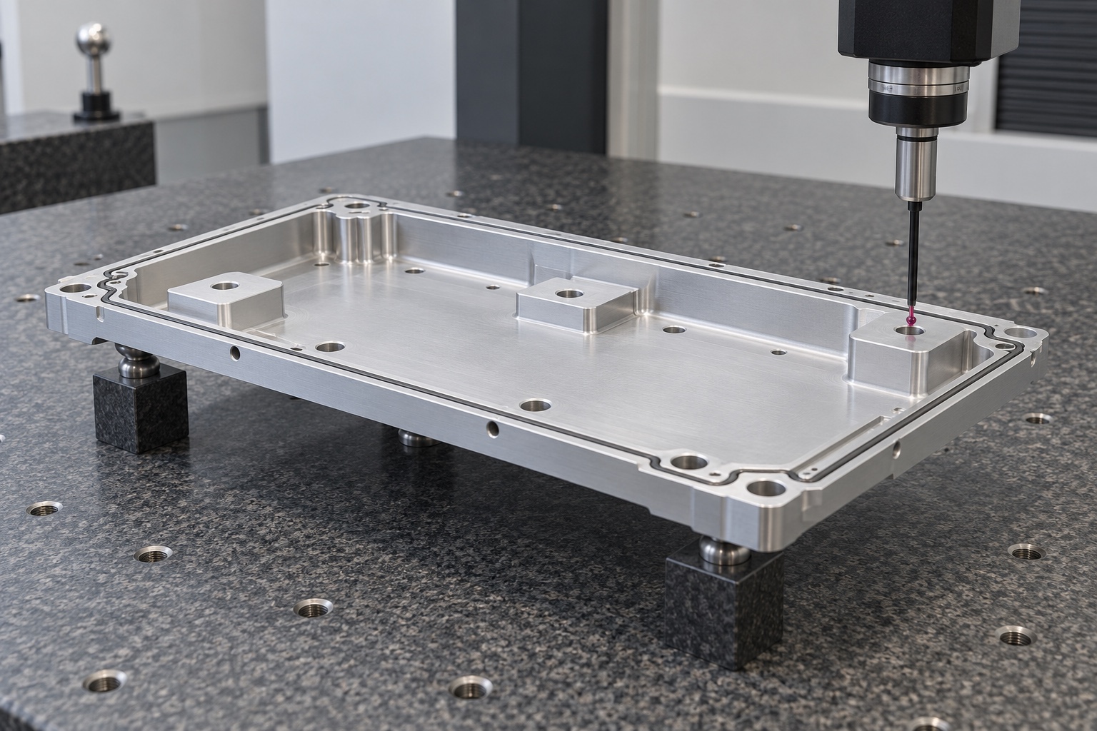
Measure the functional geometry deliberately
A first-article plan can cover material identity, mounting features, support height, the selected flatness characteristics, locating-hole positions, groove geometry and port access. Choose instruments and fixtures capable of resolving the specified features. Record support locations and distinguish a local thickness reading from a complete surface evaluation. Map results to drawing characteristics so a later revision can be reviewed without guessing what was measured. Inspect after the operations that can change the accepted features. A report should identify inaccessible regions or method limitations rather than silently treating them as verified.
Specify assembly trials separately
An assembled vacuum trial needs an agreed cartridge or surrogate, gasket, fitting configuration, source, measurement location, stabilization period and acceptance criterion. Leakage, retained vacuum and resistance to a specified disturbance are different observations. Determine which one the order actually requires. A successful bare-plate dimensional report does not establish any of them. Conversely, an assembly that appears to hold a sample does not confirm every drawing feature. If failure occurs, preserve the test configuration and identify whether the likely cause is the part, gasket, cartridge, connection or procedure before changing production dimensions.
Protect passages and support surfaces
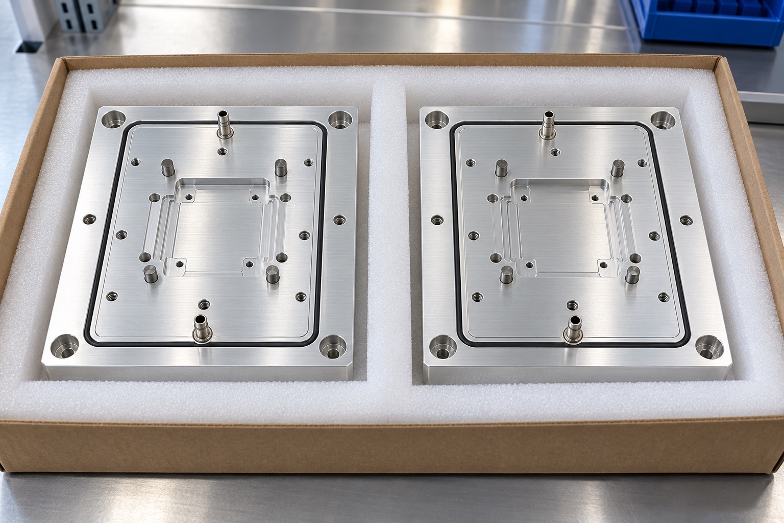
Cleaning should remove the specified machining and finishing residues without damaging the material, seal path or finished surfaces. Dry accessible passages using a compatible, agreed route. During handling, keep labels and adhesive away from support pads and sealing lands. Separate parts so a mounting corner cannot rub the working face of the next plate. Protective caps and inserts should not introduce debris or conceal an unverified passage. Identify the part number, revision and lot on the packaging. This is damage and contamination control, not an assertion of sterile delivery or a classified cleanroom process.
Build a useful RFQ and repeat-order record
Provide a controlled drawing, matching model, material condition, quantities, finish, cartridge interface, seal information and requested inspection records. List the assembly trials separately, including who supplies consumables and who approves the procedure. Resolve any disagreement between the sample, drawing and model before quoting. After approval, retain the first-article disposition, process references and authorized deviations. A later change to the gasket, cartridge or support method may justify an engineering review even if the plate outline stays the same. Clear evidence makes the repeat order about a defined configuration rather than a photograph of an earlier fixture.
Manufacturer background reference: www.schmalz.com.
FAQ
Which features locate the cartridge?
The drawing should identify the locating pins or stops, support regions and clearances. A gasket is not automatically a precise locating element, and the apparent perimeter of the cartridge does not define an approved datum scheme.
Does a flat plate guarantee a vacuum seal?
No. The cartridge, gasket, groove geometry, finish, ports and complete circuit contribute to the assembled interface. Flatness inspection and an agreed vacuum trial provide different evidence and should not be substituted for each other.
How should leakage be checked?
Agree the assembled configuration, source, measurement location, stabilization, duration and acceptance criteria before quoting. Identify whether the requirement concerns leakage flow, retained vacuum or another defined observation; a general instruction to test vacuum is incomplete.
Can the fixture be anodized?
Anodizing can be reviewed when specified for the selected aluminum and application. Define masking and finished-condition dimensions, then verify the features that treatment may affect. No finish should be assumed compatible with every cleaning chemistry.
What needs deliberate burr inspection?
Port intersections, threaded entries, groove transitions and the edges of support or locating features deserve attention. Cleaning can remove residue, but it does not establish that an attached burr or an inaccessible sharp edge has been eliminated.
What should accompany the RFQ?
Send the released drawing and model, material, quantities, finish, cartridge and seal references, inspection requirements, packaging expectations and any separately defined assembly trial. Include sample availability and the required drawing revision for repeat orders.

tanghangyun@oemach.com