

Why the adapter deserves its own specification
A diagnostic pipetting head uses mechanical interfaces to locate a disposable tip, support a seal and provide a controlled pneumatic connection. The machined adapter is only one element, but its flange, bore and external seat influence how consistently the consumable attaches. An adapter that looks smooth may still seat unevenly or contact the wrong part of the tip. A useful manufacturing drawing therefore identifies the functional contact zones and their relationships. It should distinguish locating features, sealing surfaces and clearance geometry rather than assign the same tolerance to every cylindrical surface.

Start with the actual tip and head
Before selecting a tool path, review the released tip interface, mating head and assembly sequence. Establish whether the tip is located by a taper, shoulder, sleeve or a dedicated locking mechanism. Some systems use elastomer seals, while others rely on features of the consumable itself. These designs are not interchangeable. Obtain approved interface data and representative mating samples where a fit trial is required. A generic photograph is useful context but cannot establish compatibility. Confirm insertion direction, release travel, surrounding clearances and whether the adapter is a serviceable part or permanently retained in the head.
Separate locating and sealing requirements
A locating diameter guides the component; a sealing band controls contact with a specified seal or consumable. A shoulder may set axial height without being part of the seal. Mark these roles on the drawing so polishing, edge breaking and inspection preserve the correct surfaces. A tool mark across a sealing band can matter differently from a mark in a relieved area. Define which transitions must remain sharp enough to locate and which need lead-in radii to protect the mating tip. The designer determines the seal concept and allowable contact condition; the supplier converts that definition into a repeatable process.
Choose a measurable datum system
For a flanged sleeve, a mounting face can establish axial position and an accessible locating diameter can define the working axis. Relate the bore, external seating profile and flange to this system. Use the geometrical controls and inspection methods specified by the drawing instead of treating every coaxial relationship as a generic concentricity requirement. A dial-indicator reading on an unsupported thin sleeve is not automatically equivalent to a complete geometric assessment. Define support, rotation and contact locations. Where the final head uses a different mounting condition, explain how the part-level check relates to the assembly.
Material and process compatibility
316L stainless steel is one possible material for a robust turned adapter, but selection depends on the intended environment, cleaning chemistry and contact conditions. A device may instead require another alloy, polymer or coating. Confirm the precise grade, stock condition and certification requirements before machining. Distinguish surfaces exposed to sample, aerosol, air or only the surrounding mechanism. These exposure categories can change cleaning and verification needs. Retain material-lot identity after bar cutting. Do not infer that a material certificate proves biological suitability, sterility or compatibility with every reagent; those conclusions require the device team's defined assessment.
Plan turning around the functional axis
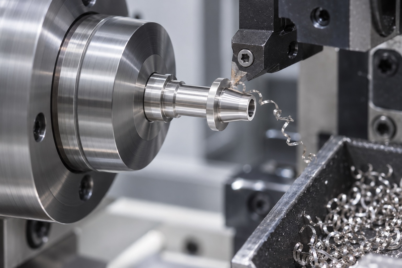
A controlled turning sequence can establish the locating diameter, flange face and external seat in one primary setup. Drill or bore the axial passage with a strategy suited to its diameter, depth and required surface condition. Manage tool reach, chip evacuation and heat so the sleeve is not pushed away from the intended axis. If the part needs a second operation, use a controlled soft collet or equivalent fixture and verify the transferred reference. Thin walls require attention to clamping deformation. A dimension that passes while the part is compressed may change after release.
Control the seal profile and transitions
A short tapered seat is defined by more than its largest diameter. Its profile, axial position, contact length and transition to adjacent reliefs can influence how the mating part settles. State the relevant profile and surface requirements in inspectable terms. An optical profile trace can help examine accessible geometry; the equipment and setup still need to resolve the specified features. Avoid selecting a universal roughness value without a functional reason. If a seal band is finished separately, verify that the operation preserves its relationship to the mounting features rather than only improving visual appearance.
Remove burrs without changing the interface
Axial-bore entries, small cross-features and groove edges need deliberate burr control. Loose metal can obstruct a passage or damage a mating component, while excessive polishing can enlarge a bore or round a seating shoulder. Define acceptable edges and the inspection access for hidden areas. When the design includes a narrow internal step, review whether the intended tool and deburring method can reach it. Cleaning removes residue; it does not prove that an attached burr has been removed. Inspect after the final surface operation, because that step can introduce particles or alter an already checked edge.
Build a first-article inspection plan
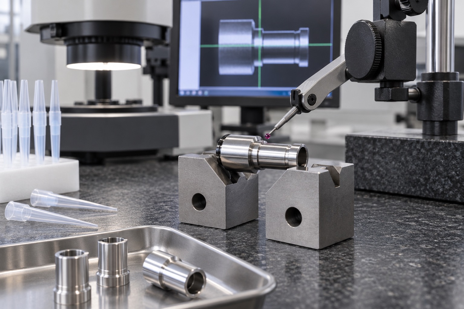
The plan can include material identity, flange thickness, mounting-face condition, locating diameter, bore size, seat profile and the relationships between those features. Combine suitable optical, contact and gauging methods rather than expect one instrument to answer every question. Record the fixture condition and distinguish direct measurements from calculated results. Use controlled mating samples for a fit trial, with defined insertion depth and assembly state. Inspect the finished condition if passivation or another treatment is specified. Reports should connect each result to a drawing characteristic, revision and material lot so repeated orders can be evaluated consistently.
Define functional trials separately
An agreed fixture may assess tip retention, release, pneumatic leakage or repeatable seating, but its configuration and acceptance criteria must come from the equipment specification. Identify the tip model and lot, seals, mounting torque, test medium, pressure and hold time where relevant. Do not translate a dimensional pass into a claim of pipetting accuracy. Dispensed-volume verification also depends on the complete channel, software, liquid, environment and operating method. Keep part-level measurements, assembly trials and system performance records separate while linking them through traceability. This makes a failed trial easier to investigate without discarding useful geometric evidence.
Clean handling and protected delivery
After machining, remove chips, coolant and finishing residues with a process compatible with the part and the agreed cleanliness level. Dry passages and protect them against contamination during handling. Use separate compartments or protective caps that do not shed material or load a delicate seat. Do not place adhesive labels on functional contact surfaces. Record the part number, revision, quantity and lot on the packaging documentation. A clean protective tray is not a sterile barrier. Any specified particle, residue or microbiological acceptance requirement needs its own agreed process and verification method rather than a general statement that the parts are clean.
Prepare the RFQ and repeat-order package
Send a controlled drawing, matching STEP model, material requirement, quantities, finish and inspection expectations. Include approved tip-interface data and available mating parts if a fit or leakage trial is requested. Identify features that must be measured after treatment and the records expected with delivery. Manufacturer descriptions of pipetting systems illustrate that alignment and sealing can depend on dedicated interface designs; they do not establish interchangeability with this example. For repeat production, retain the accepted first article, fixture references and change history. Reassess modifications to stock, tooling, deburring or treatment against the same released functional requirements.

Manufacturer references on system-specific tip sealing and alignment: Hamilton; Tecan.
FAQ
Which dimensions are usually critical?
The locating diameter, mounting face, axial bore, seating profile and their geometric relationships are common priorities. The equipment drawing identifies the actual contact zones and acceptance criteria; an illustration does not define tolerances.
Does a smooth surface guarantee a leak-free joint?
No. Seal concept, contact geometry, mating tip, assembly condition and surface damage all matter. If leakage is a requirement, specify a separate agreed test with a defined fixture and acceptance limit.
Can 316L be used for every diagnostic adapter?
No. It is one possible material. The device designer confirms grade, exposure, cleaning compatibility, treatment and any biological or reagent-related requirements for the intended application.
How can a thin sleeve be inspected reliably?
Define its support and free-state condition, avoid excessive clamping and use measurement methods suited to the required geometry. Record contact points, fixture references and the relationship to the drawing datums.
What is needed for a tip-fit trial?
Approved tip and head interfaces, representative consumables, seals where applicable, assembly instructions and measurable acceptance conditions. Retention, release and leakage are different observations and should be recorded separately.
What documents should accompany an RFQ?
Provide drawings, models, revision, material, quantities, treatment, critical features, cleanliness level, inspection reports and any requested functional trial. State whether the order is a prototype or an approved repeat build.
tanghangyun@oemach.com