
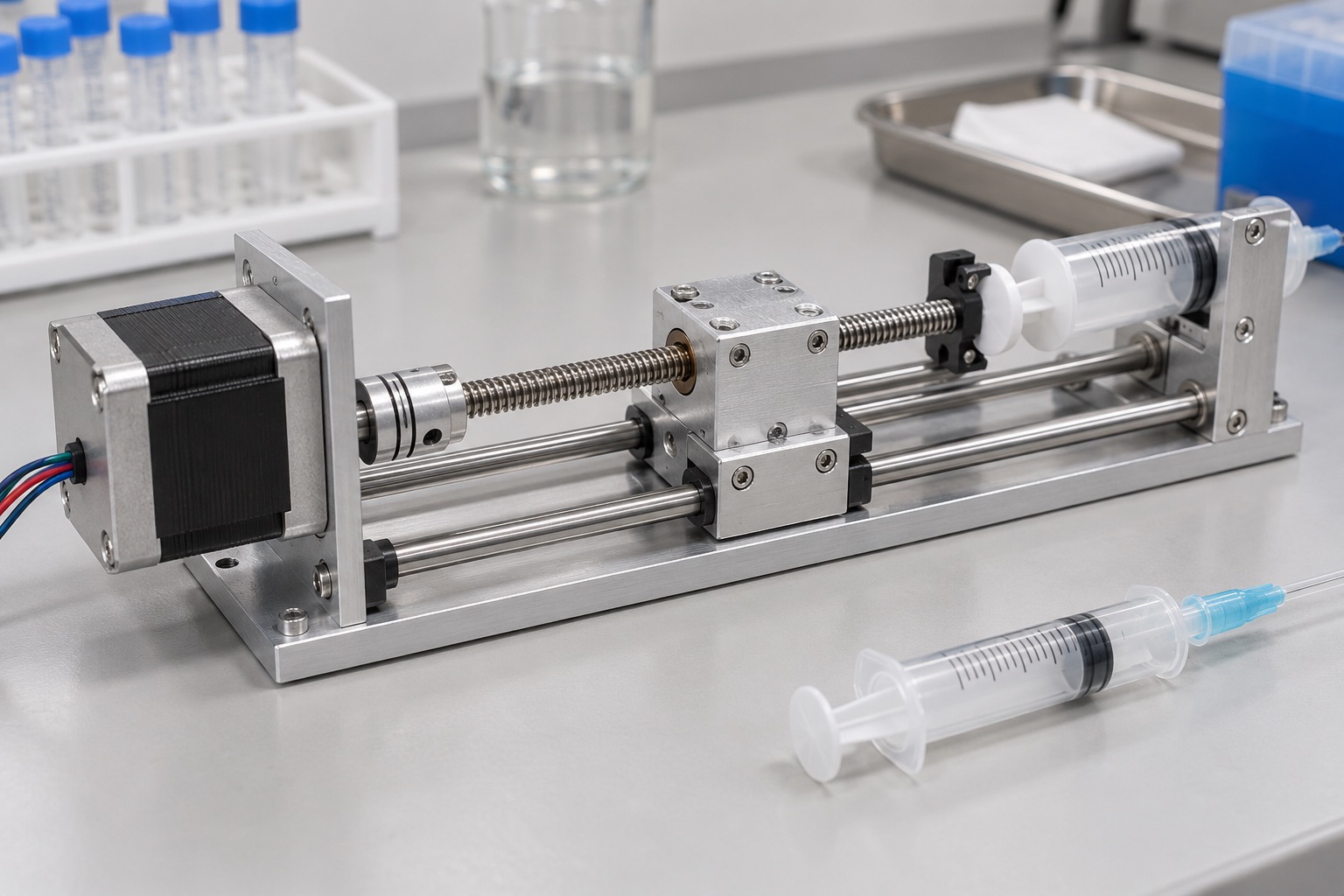
CNC Machining Syringe Pump Drive Supports: Motor Registers, Lead-Screw Alignment and Inspection
The small parts behind controlled motion
A syringe pump drive combines a motor, screw, nut, guide and pusher. CNC-machined mounts and bearing blocks connect these components to the instrument structure. Their dimensions influence whether the assembled carriage travels freely or encounters changing resistance. This article discusses mechanical manufacturing interfaces, not a validated dosing specification. The device manufacturer defines pumping performance, alarms and verification. For procurement, the useful starting point is a drawing that shows how the motor register, bearing axis and guide reference relate to one another rather than a list of isolated tight dimensions.

Map the assembly before choosing tolerances
Review the motion path from the motor face to the pusher. Identify the register that locates the motor, the bore or seat that locates the bearing, and the surfaces that position the guide. Clearance holes normally provide clamping; they do not automatically provide precise location. Confirm whether dowels, shoulders or a specified assembly adjustment establish alignment. Define screw travel, assembly access and fastener clearance. Leave room for the chosen coupling and its installation procedure. A mount that is easy to inspect but impossible to align inside the enclosure is an incomplete design.
Functional datums and tolerance stack
A practical datum system can start with the frame contact pads, followed by a side reference and a locating feature. Relate bore position and face orientation to those datums. Include the mating guide and bearing support in the stack calculation instead of assigning a universal tolerance to every feature. A dimension report on one bracket cannot establish alignment of the entire drive. Where adjustment is intentional, define its range and the acceptance check after tightening. Record the free-state and clamped-state assumptions so production and inspection do not measure different conditions.
Material, stock and surface treatment
6061 aluminum can be considered for a lightweight internal support; steel may suit loaded bearing features, while engineering plastics may be used for selected isolating components. The designer specifies alloy, condition and environmental compatibility. Inspect raw stock identification and retain the material lot through machining. Anodizing can change the size and contact condition of precision features. Agree which bores, datum pads, threads or grounding interfaces are masked, and specify whether dimensions apply before or after treatment. A cosmetic color requirement alone does not define an acceptable functional coating.
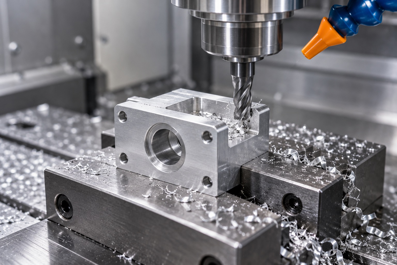
Establish a stable CNC sequence
Rough the main shape while leaving stock on locating surfaces. Establish reference pads, then finish the motor register, bearing seat and bolt pattern using a controlled setup or a documented transfer of datums. Thin feet and tall walls require support that avoids bending under clamping force. Cutting access, tool reach and chip evacuation should be reviewed before choosing a compact geometry. Keep cutting forces away from unsupported walls. If a bore is finished in a later setup, verify the relationship to the base instead of relying only on its diameter.
Edges, threads and moving clearances
Remove loose burrs around holes, pockets and screw entries while preserving the locating shoulder. A generous edge break can reduce the effective seating surface or interfere with a bearing chamfer, so the edge requirement should be explicit. Check screw lengths against usable thread depth and moving-carriage clearance. Keep abrasive debris away from bearing seats and guide interfaces. Lubrication is specified for the selected motion assembly; packaging a machined bracket with an unspecified lubricant may contaminate surfaces or conflict with the assembly process. Protect precision contacts during deburring and handling.
Measure geometry and verify assembly separately
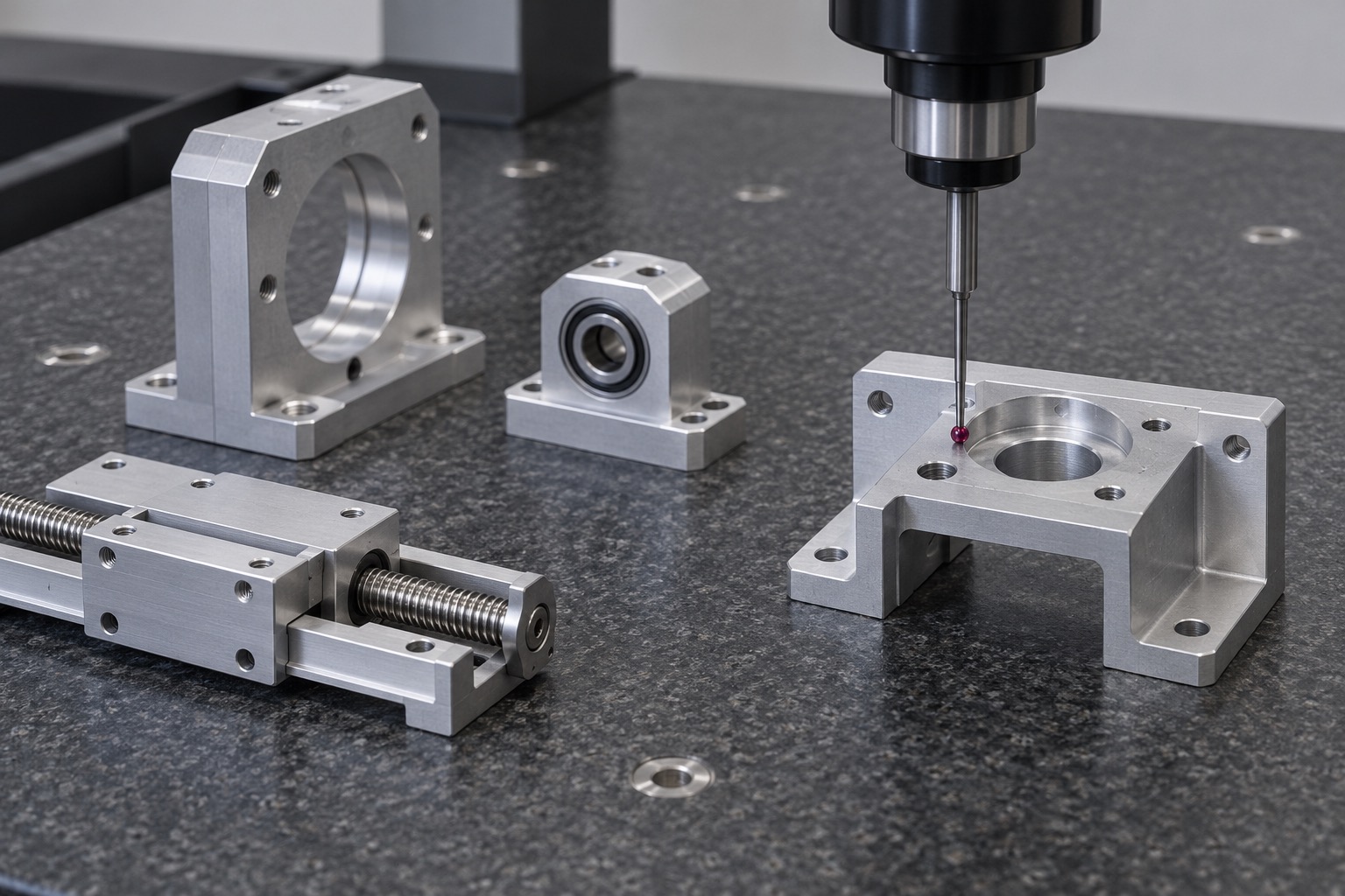
A first-article report can cover contact-pad flatness, motor-face orientation, bore diameter, bore position, dowel holes and threads. Use drawing datums and document how the part is supported. Suitable CMM or optical methods may be combined with gauges for local features. After coating, recheck interfaces that determine fit. Separately, an agreed assembly test can assess full-stroke freedom of movement and interference with the selected motor, guide and screw. Those observations are mechanical checks; flow accuracy and occlusion detection require the device manufacturer's test procedures.
Cleaning, delivery and change control
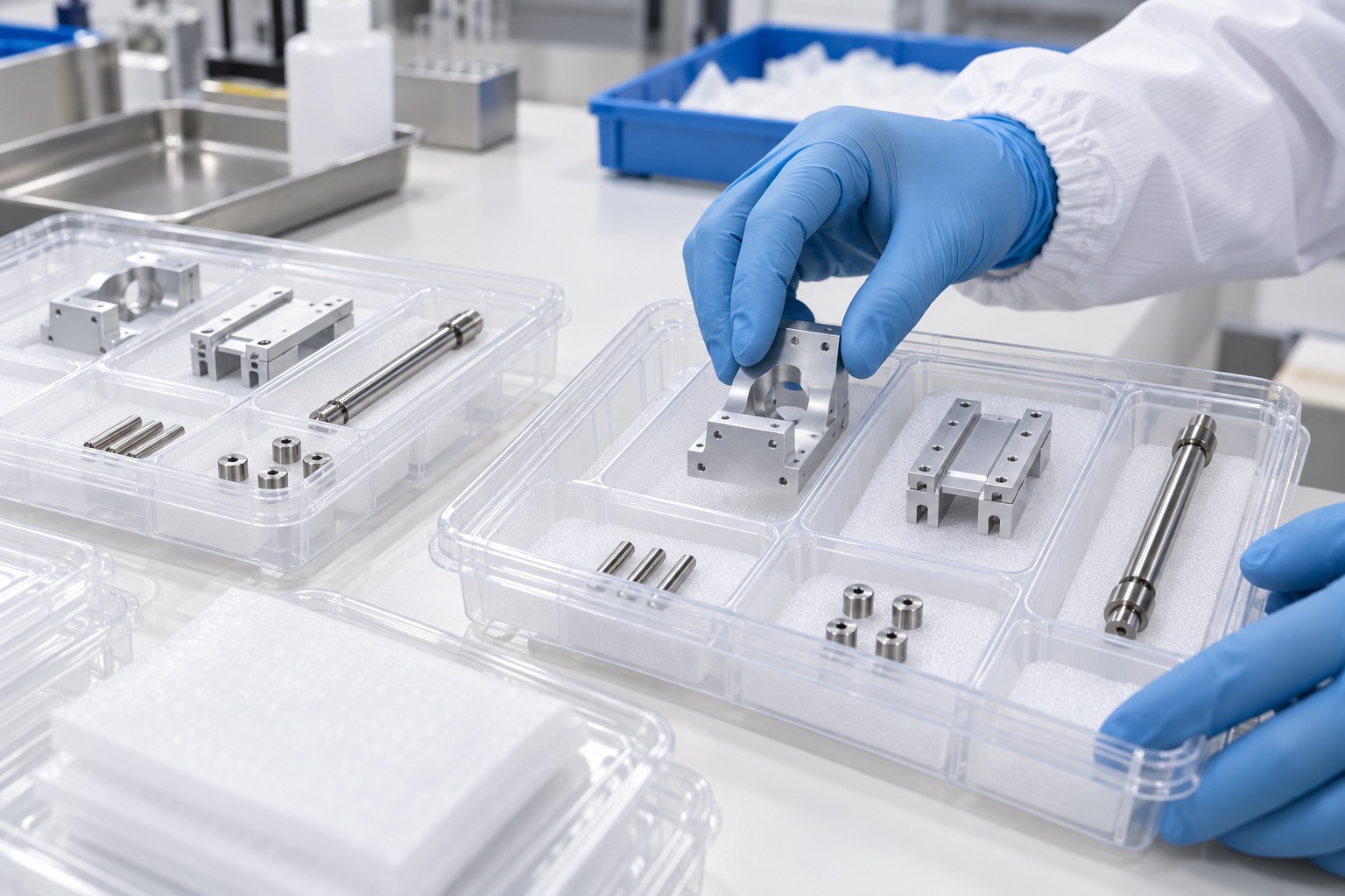
Remove chips, coolant and abrasive residues from bores, pockets and threads using a compatible cleaning process. Dry parts before placing them in separate protective compartments. Packaging should prevent polished bores and datum pads rubbing against other parts; clean packaging does not imply sterile delivery. Include the part number, revision, material lot and inspection status on the lot record. Changes to machining sequence, coating, locating geometry or approved deviations should be reviewed for their effect on the assembly. Keep the released drawing and inspection plan linked.
A useful RFQ package
Send the controlled drawing and matching model, prototype and repeat-order quantities, material condition, treatment specification and critical interface requirements. Provide relevant motor, guide, bearing and fastener information when an assembly check is requested. Specify coating masks, cleaning, documentation and acceptance conditions instead of asking for precision in general terms. This allows the supplier to estimate machining, inspection and fixtures with visible assumptions. Manufacturer installation guidance also emphasizes screw alignment, support arrangement and nut selection; apply the instructions for the actual components selected, not a generic illustration.
FAQ
Which bracket features normally control alignment?
The motor register, bearing seat, guide references and frame contact pads are typical locating features. The drawing must show their relationship; screw clearance holes alone usually serve clamping.
Does a CMM report prove dosing accuracy?
No. It documents specified geometry. The device manufacturer verifies the assembled pump's delivery performance, alarms and other system requirements with its own defined procedures.
Should every dimension have the same tight tolerance?
No. Allocate tolerances from the functional stack and inspection access. Nonlocating clearances can often have different requirements from bores, datum pads and mating faces.
What needs checking after anodizing?
Recheck specified locating bores, contact pads, threads and mating dimensions. Agree masks and the stage at which acceptance dimensions apply before the parts are manufactured.
Can the supplier perform an assembly motion check?
Yes, when the mating components, mounting sequence and acceptance criteria are supplied. Define travel, tightening conditions and permitted resistance or interference in the inspection plan.
What documents help obtain a usable quote?
Provide drawings, models, material condition, quantity, finish, interface details, cleaning requirements, required reports and any agreed assembly check. Separate prototype approval from repeat production.
Technical reference: Thomson motorized lead screw installation guidance
tanghangyun@oemach.com