
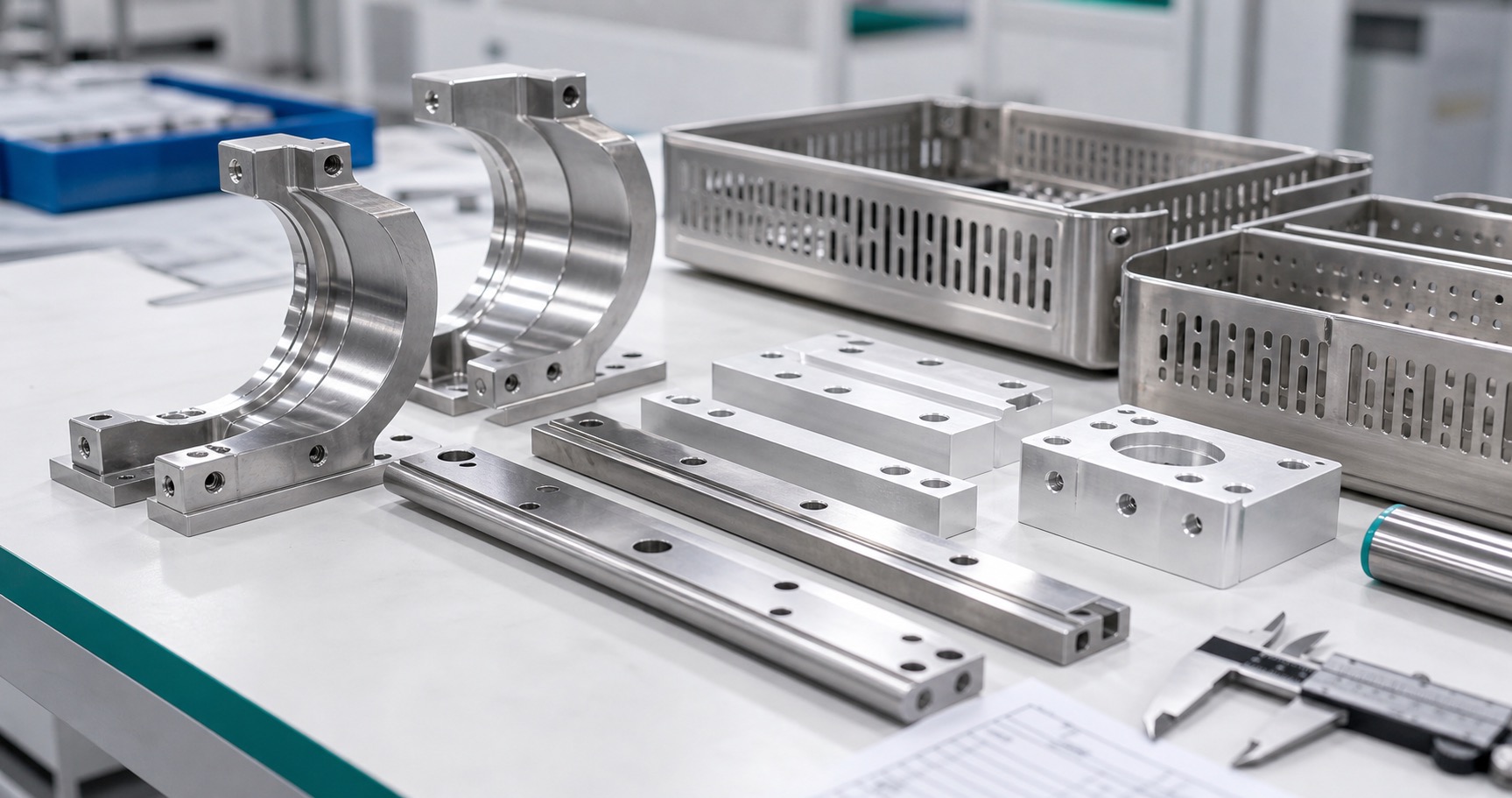
CNC Machining Sterilization Equipment Sensor Brackets: Heat Resistance, Drainage and Validation Datums
Why sterilizer brackets deserve process control
Sensor brackets, validation probe holders and small support rails inside sterilization equipment may look like simple hardware, but they influence how temperature probes, pressure lines, trays or shields stay positioned during repeated cycles. A loose bracket can shift a sensor away from the intended measurement point, while a poorly drained pocket can trap residue. The machining plan should therefore consider heat, moisture, cleaning chemistry and repeatable assembly rather than treating the part as a generic bracket.

Start with the operating environment
Before quoting, confirm whether the part sees saturated steam, dry heat, cleaning chemicals, repeated washdown, vacuum pulses or only external service conditions. Cycle temperature, dwell time, pressure, condensate flow and cleaning exposure affect material, finish and inspection choices. If the bracket supports a validation probe, the equipment manufacturer should define probe location, allowable movement and the calibration or qualification method.
Material selection
PEEK, PPSU, stainless steel and aluminum may all appear in sterilization equipment, but they serve different functions. PEEK can offer high-temperature strength and chemical resistance with low mass. Stainless steel may be preferred for robust rails, threaded features or repeated handling. Aluminum needs careful finish review in wet or chemically aggressive areas. Material certificates and grade definitions should be included with the purchase package.
Thermal stability and stack-up
Repeated heating and cooling can change how a bracket fits relative to a chamber wall, tray rail or sensor body. The drawing should identify which dimensions control the probe location at assembly and which features merely provide clearance. If polymer and metal parts are combined, thermal expansion differences can change clamp load or hole alignment. The supplier can machine the geometry, but the device team owns thermal validation.
Drainage and residue control
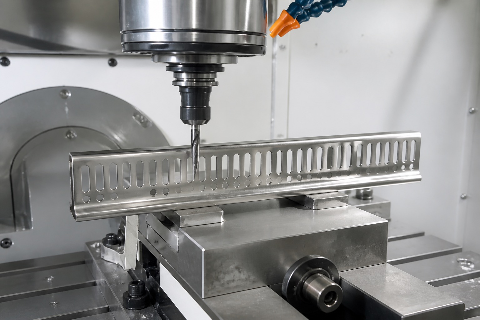
Sterilization equipment parts should avoid blind pockets, sharp internal corners and horizontal ledges that trap condensate or debris unless the design intentionally needs them. Slots, reliefs and edge breaks should be reviewed for drainage and cleanability. Deburring must remove loose edges without rounding datum surfaces or sensor seating features.
Machining sequence and fixturing
A stable CNC sequence establishes datums, roughs pockets or slots, then finishes sensor bores, mounting holes, rails and contact pads from controlled references. Polymer parts need tool paths that manage heat and avoid smearing. Stainless parts need burr control at slots and threads. Fixtures should hold the part without marking cleanable surfaces or changing free-state geometry.
Inspection priorities
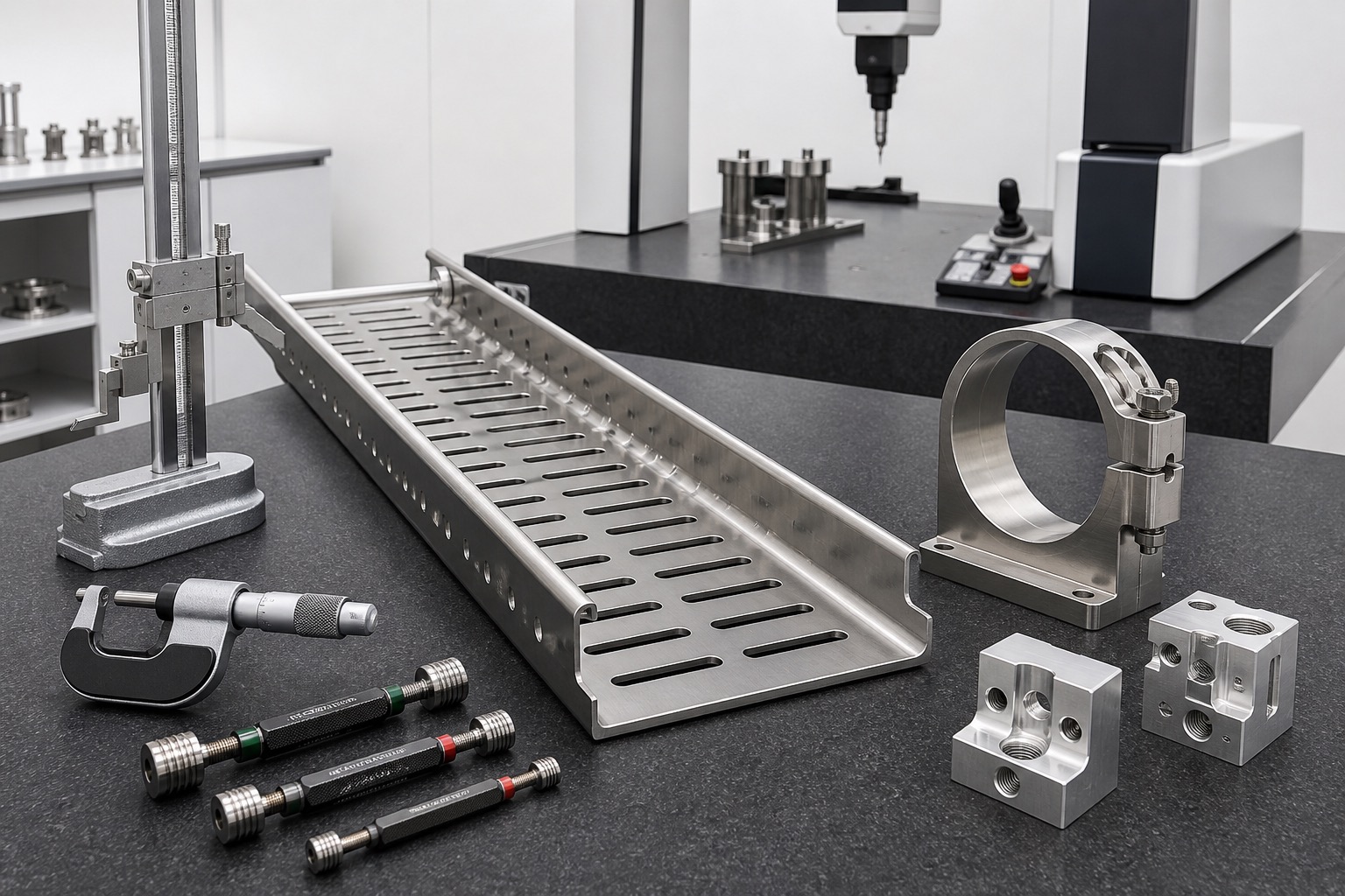
A first-article plan can include probe bore position, mounting hole location, rail straightness, slot width, contact pad flatness, thread gauges, surface finish checks and visual review of drainage paths. For polymer brackets, measure after the part has cooled and stabilized. Inspection data should reference the same datum system used by the equipment assembly.
Cleaning and packaging
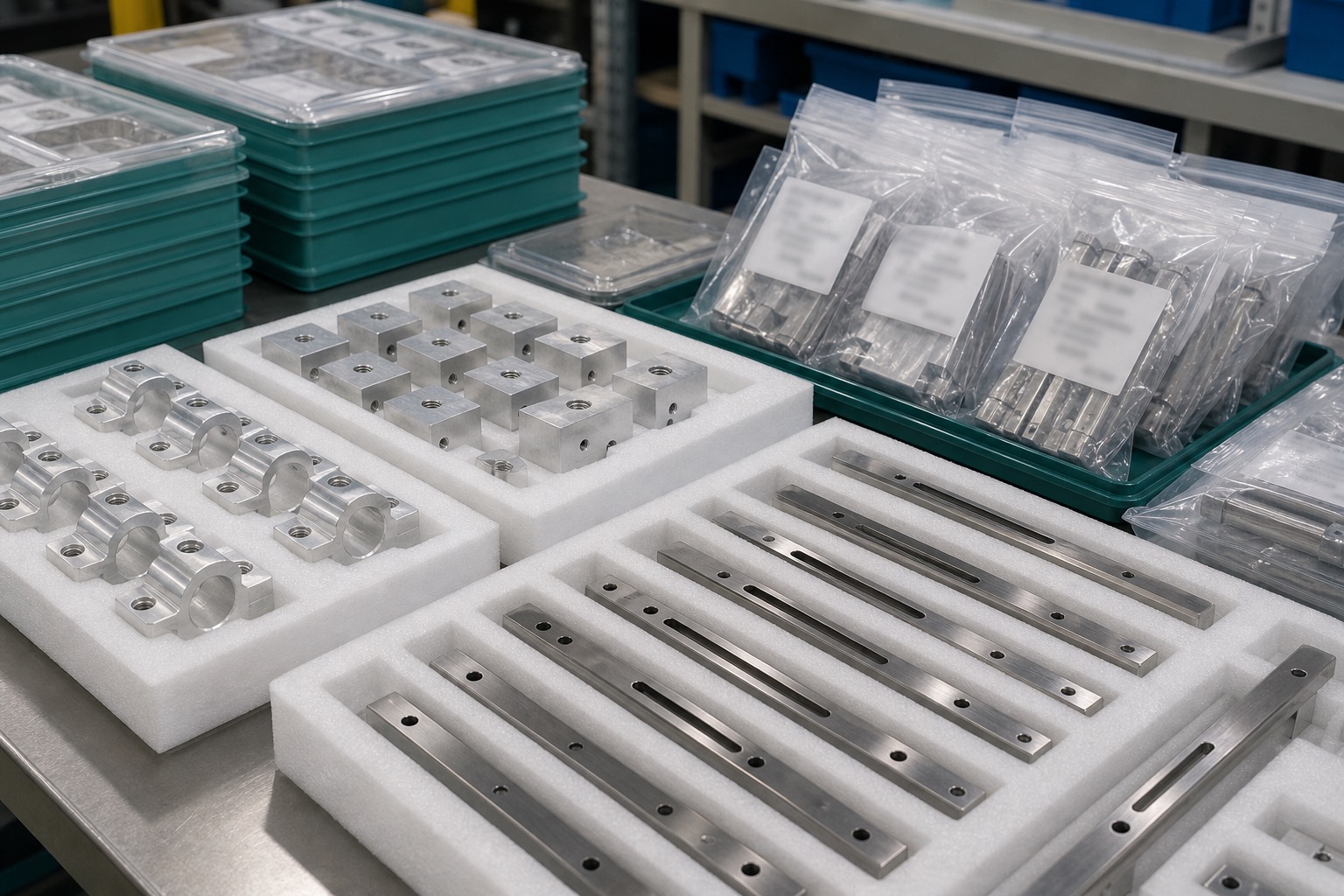
After machining, remove chips, coolant, plastic dust, abrasive residue and loose particles from bores, slots and threads. Parts should be packaged to protect probe seats, cleanable surfaces and edges from rubbing damage. Labels should identify part number, revision, material lot, inspection status and any agreed cleaning level. Do not claim sterility unless a validated sterile packaging process is part of the order.
RFQ handoff
A useful RFQ includes drawings, 3D models, operating temperature, material and certificate requirements, finish, probe or sensor interface data, critical tolerances, quantities, cleaning expectations and inspection records. For validation hardware, include how the equipment team will confirm sensor position and cycle performance.
FAQ
Can a machined bracket validate a sterilization cycle?
No. It can hold a probe or sensor repeatably; cycle validation and sterilization performance remain with the equipment manufacturer.
Which materials are common?
PEEK, PPSU, stainless steel and finished aluminum may be used depending on temperature, cleaning exposure, load and electrical needs.
What features are usually critical?
Probe bores, mounting holes, datum pads, rail straightness, slot width, drainage paths and threaded features are common critical points.
Why does drainage matter?
Poorly designed pockets can trap condensate, debris or cleaning residue, so slots, reliefs and edges should support cleaning and drying.
How are polymer parts inspected?
Measure after cooling and stabilization, and control burrs or smearing around bores, slots and contact surfaces.
What should be included in the RFQ?
Send drawings, models, temperature exposure, material, finish, probe interface, tolerances, quantities, cleaning and inspection needs.