
CNC Machining Ultrasound Probe Positioning Fixtures: Clamp Loads, Acoustic Windows and Inspection Datums
Why fixture geometry matters
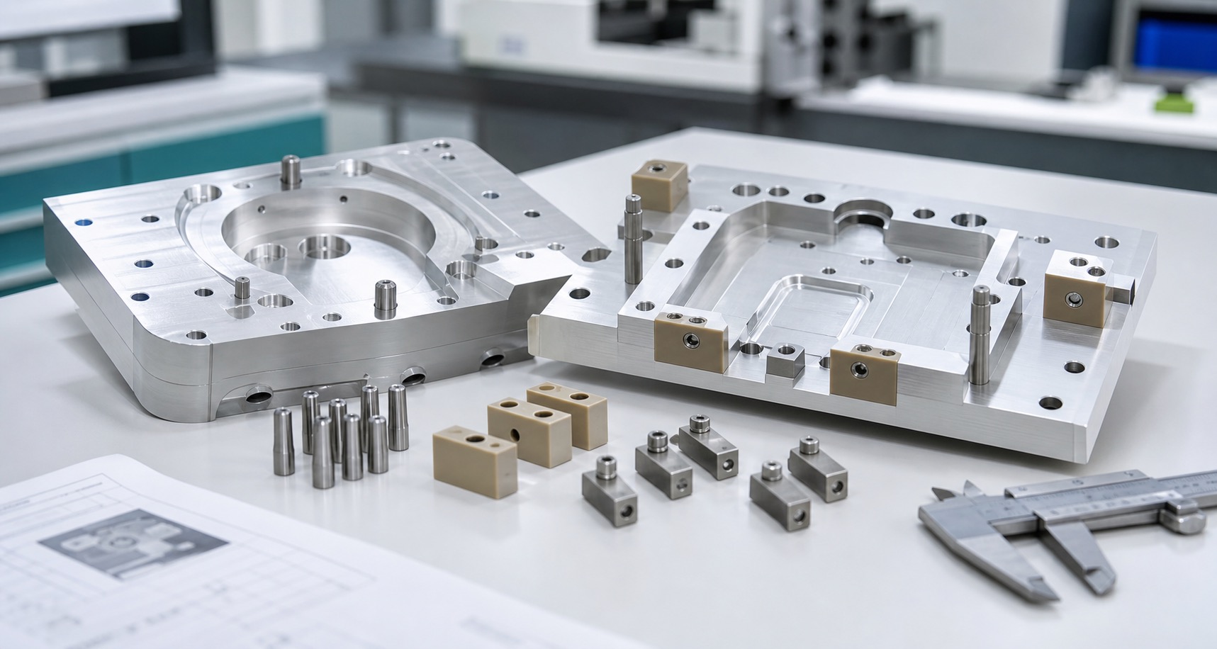
Ultrasound probe positioning fixtures are often used during assembly, inspection, service, calibration or production testing. They hold a probe or probe subassembly in a known position while leaving the acoustic face, cable exit, strain relief and reference surfaces accessible. A fixture that looks simple can still affect measurement repeatability if its nest, clamp arm or stop face shifts under load. For medical imaging equipment, the machining supplier should treat the fixture as a measurement interface, not a casual shop aid.

Define the probe datum system
A useful drawing identifies which surfaces locate the probe, which edges only provide clearance and which areas must never contact an acoustic lens or delicate housing. The datum scheme should match the way the probe will be seated in the test or assembly process. If a soft insert, polymer pad or removable stop is used, its thickness and replacement tolerance should be included in the stack. The machine shop needs the real locating logic before selecting a fixture strategy.
Control clamp load and contact area
Clamp force should be sufficient to hold the probe repeatably without distorting a plastic shell, marring a finished surface or transferring stress into the acoustic window. CNC-machined clamp arms, pivots and stop blocks need flat contact faces, controlled radii and stable screw relationships. If torque-limited screws, spring plungers or elastomer pads are used, their effect on repeatability should be reviewed with the equipment team.
Material and finish choices
Aluminum is common for lightweight test fixtures, stainless steel may be preferred for wear or cleaning resistance, and titanium may be useful where high strength and low mass are important. Engineering plastics can protect cosmetic surfaces but may move with temperature and cleaning agents. Surface finish should be specified by function: sliding contact, optical inspection, cleaning and corrosion resistance do not all require the same finish.
Acoustic access and clearance
The fixture must leave the acoustic window or coupling area clear for the intended test. Avoid sharp edges near lens material, gel channels or membrane features. Cable exit paths need enough radius and strain relief so repeated loading does not bend the cable at the same point. If the fixture is used with water, gel or cleaning fluid, drainage and residue traps should be considered during the design review.
Machining sequence
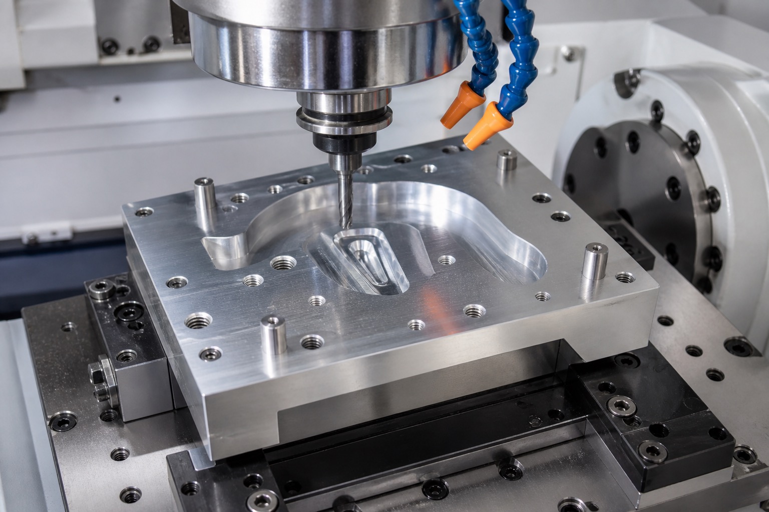
A stable process usually establishes the base datums, machines the probe nest and stop faces, then finishes clamp pockets, pivot bores and threaded holes from controlled references. Thin clamp arms and long slots can move after roughing, so finish passes should occur after stress is released. Burr control matters near probe contact edges and near any sliding or hinged clamp feature.
Inspection plan
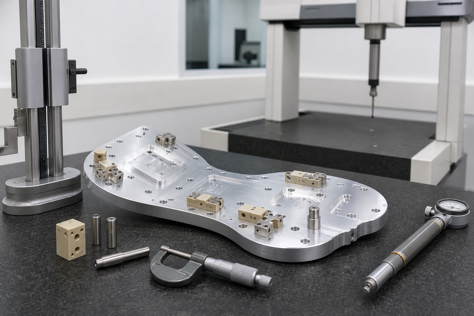
Inspection should focus on the features that control probe location: nest width, stop face position, clamp arm height, pivot bore alignment, threaded hole location, flatness of the base and relationship between acoustic access and probe datums. CMM, optical tools and functional gauges can be combined. A first article should record the measurement condition, insert material and any customer-supplied master probe or gauge.
Cleaning and packaging
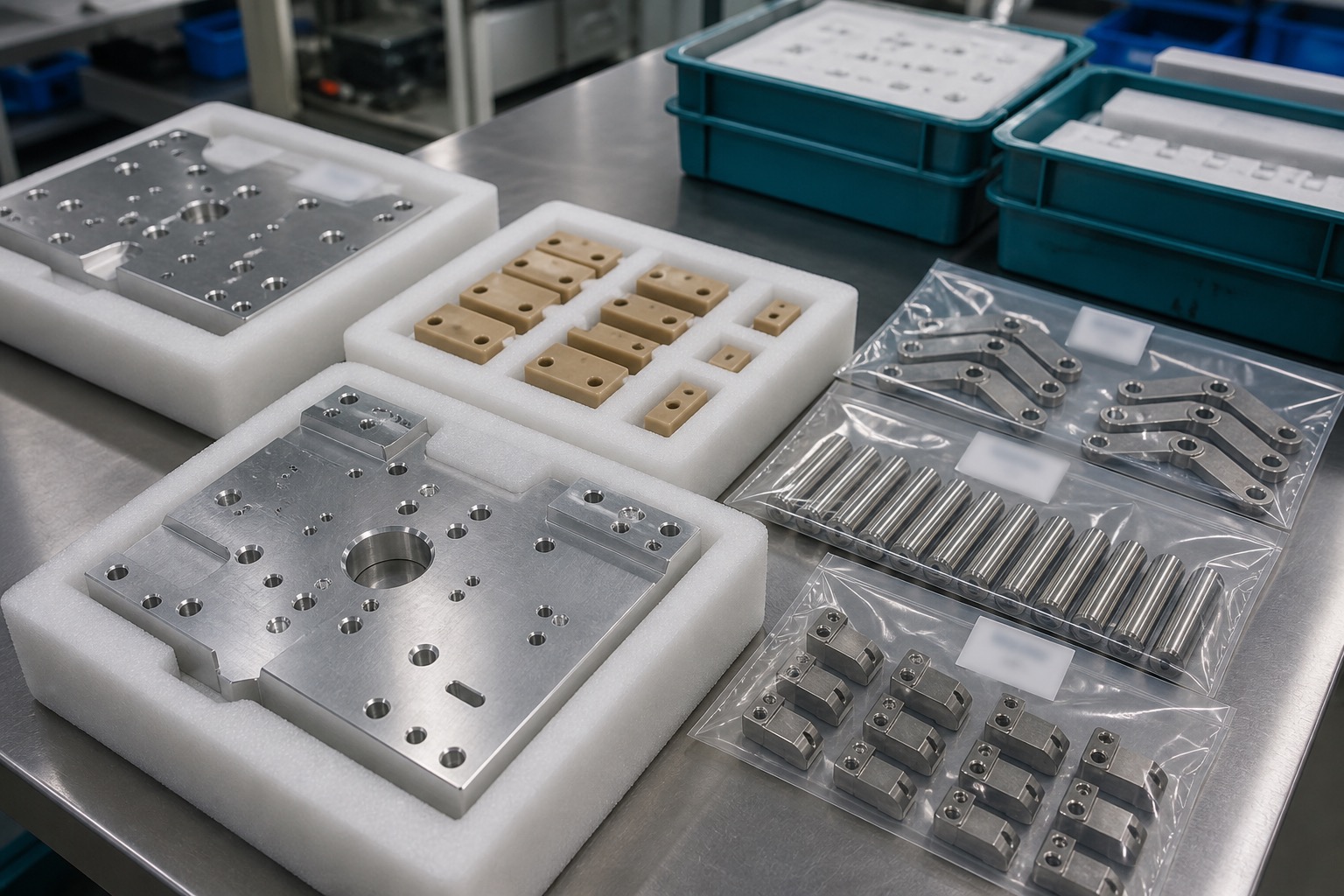
Fixture parts should be cleaned to remove chips, coolant, abrasive residue and loose particles from pockets, slots and threaded holes. Contact surfaces should be protected during shipment because a small dent on a stop face can affect repeatability. Packaging can include separated bags, trays, labels for revision and material lot, and notes for inserts or replaceable pads.
RFQ handoff
A complete RFQ includes 2D drawings, 3D models, probe interface information, material, finish, clamp hardware, insert material, target repeatability, quantity, cleaning requirements and inspection reports. If the fixture supports a regulated medical device process, the device manufacturer should define qualification and validation requirements separately from the machining order.
FAQ
Can a fixture certify an ultrasound probe?
No. A machined fixture supports repeatable positioning; device performance, acoustic validation and regulatory qualification remain with the equipment manufacturer.
Which features should be critical?
Probe nest surfaces, stop faces, clamp contact areas, pivot bores, base datums and acoustic access clearance are typical critical features.
How is clamp damage avoided?
Use defined contact areas, controlled radii, pads or inserts when needed, and torque or spring limits supplied by the device team.
What materials are common?
Aluminum, stainless steel, titanium and engineering plastics may be used depending on wear, cleaning, weight and contact-surface requirements.
How should acoustic clearance be checked?
Inspect the relationship between probe datums and the open window or coupling area using CMM, optical tools or a customer-supplied gauge.
What should be included in the RFQ?
Send drawings, models, probe interface data, materials, finish, clamp hardware, repeatability target, quantities, cleanliness and inspection needs.