
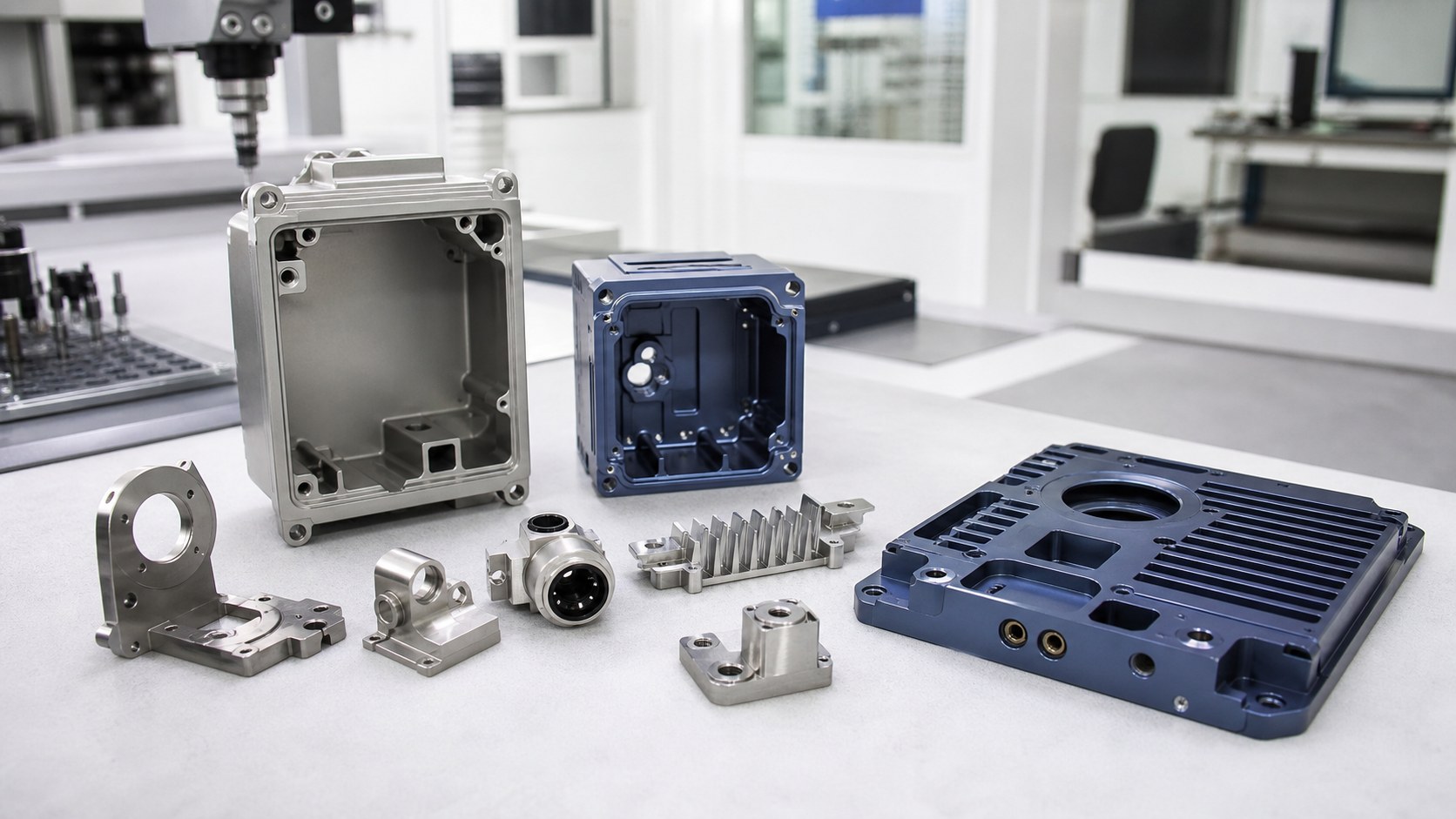
CNC Machining Diagnostic Analyzer Sensor Brackets: Optical Datums, Gasket Grooves and Clean Assembly
Why diagnostic analyzer brackets matter
Clinical diagnostic instruments depend on repeatable sample motion, optical measurement and controlled fluid or consumable positioning. A CNC-machined housing or sensor bracket may not perform the assay, but it sets the relationship between light source, detector, sample tube, cartridge, cover and gasket. A small shift in a sensor datum, groove or locating face can create alignment drift, sealing variation or calibration effort. The part should therefore be controlled as a functional diagnostic interface rather than a simple frame.

Define the measurement stack
Before quoting, trace the measurement stack from sample carrier to detector. Identify optical windows, sensor bores, reference pins, tube clearances, gasket grooves, cover screws and any surface that contacts a consumable. The drawing should define which features are optical datums, which are mechanical assembly datums and which surfaces are cosmetic. If the device uses disposable cuvettes or sample tubes, the mating dimensions should be supplied with the RFQ.
Material and finish choices
Aluminum alloys, stainless steel and engineering polymers can all be used in diagnostic equipment depending on stiffness, weight, corrosion behavior, electrical isolation and finish needs. The device manufacturer should specify grade, certificate needs, coating or passivation, color, masking and whether dimensions apply before or after finishing. Black anodizing or other coatings may help stray-light management in some designs, but coating thickness can affect small bores and fitted features.
Optical datums and sensor alignment
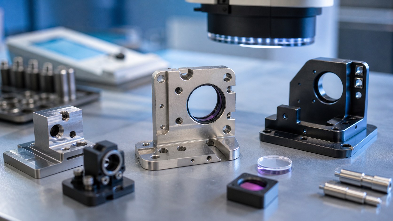
Optical performance depends on the relationship between the sensor seat, window opening, sample centerline and cover interface. The datum scheme should support CNC setup, CMM inspection and final assembly with the same reference logic. A bracket that measures from an outside profile can still fail if the sensor bore is shifted relative to the sample path. Critical optical features should be located from functional faces or pins rather than from cosmetic edges.
Gasket grooves and cover interfaces
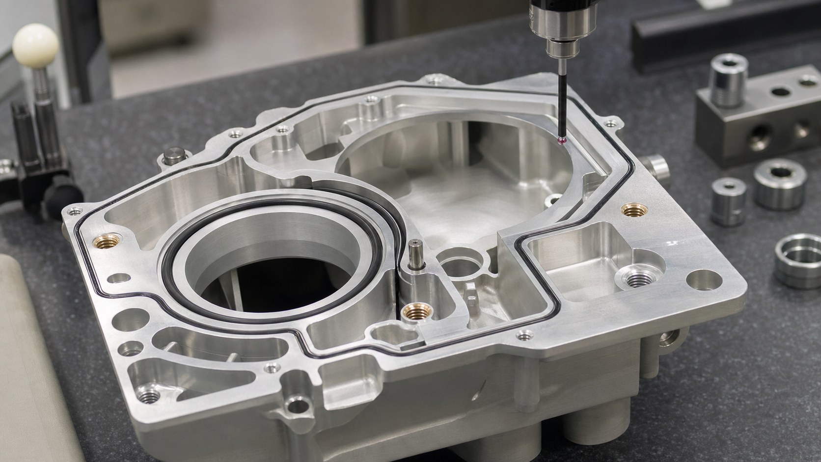
Diagnostic housings often include covers, splash shields or fluid-adjacent seals. Groove width, depth, radius, flatness and screw pattern influence gasket compression. A groove should not be rounded by broad deburring, and coating buildup should be planned if the part is anodized. The drawing should separate seal lands from appearance edges and state the support condition used for flatness measurement.
Burr and particle control
Analyzer components frequently contain small pockets, threaded holes, wire passages and optical openings that can trap chips. Loose burrs can interfere with a tube, scratch a window or create particles near a sensor. Deburring should be feature-specific: smooth user or cable-contact edges while preserving locating walls, gasket geometry and optical apertures. Magnified inspection helps verify that hidden pockets are clean.
Inspection strategy
A first-article plan can include CMM checks for sensor and tube datums, optical measurement for apertures, gauges for bores and threads, flatness checks on gasket lands and visual review under agreed lighting. Results should be tied to material lot, CNC program, fixture revision, finish batch and any approved deviation. For prototypes, assembly feedback from calibration or tube handling should be compared with dimensional data.
Cleaning and packaging
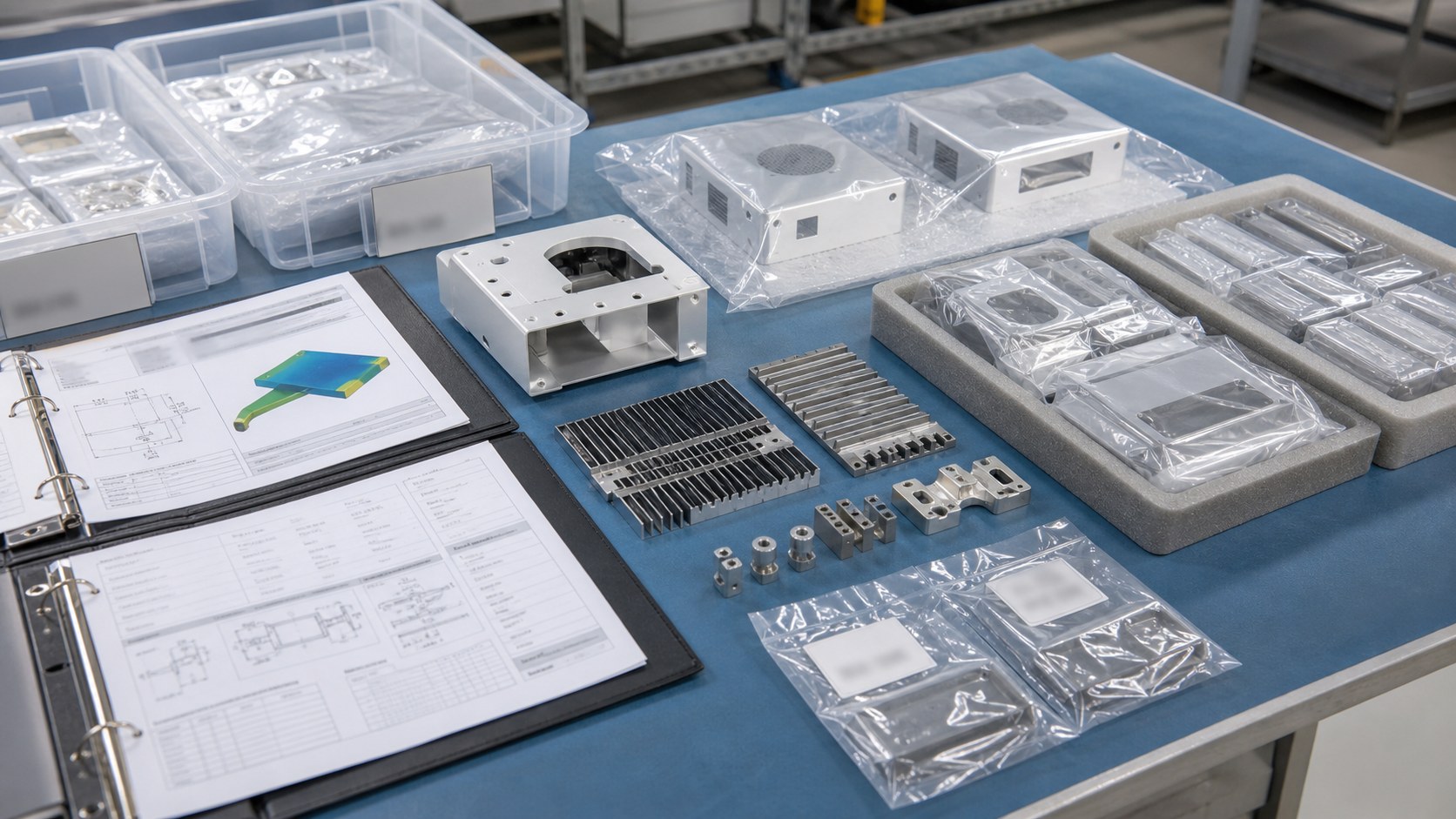
After machining and finishing, remove coolant, abrasive residue, coating dust and loose particles from pockets, grooves, threads and windows. Parts should be separated so optical faces, gasket lands and cosmetic surfaces cannot rub during shipment. Labels should show part number, revision, material lot, finish lot and inspection status. Packaging must not claim sterility unless a validated sterile process is part of the order.
RFQ handoff
A complete RFQ includes drawings, 3D models, consumable dimensions, optical datum requirements, material and finish, critical tolerances, batch quantities, cleanliness level, inspection records and any customer-supplied assembly or calibration test. Clear inputs let the machining supplier identify access, fixture and inspection risks before production begins.
FAQ
Can the bracket validate diagnostic performance?
No. It provides controlled mechanical and optical interfaces; the device manufacturer validates assay, optics, software, consumables and system performance.
Which dimensions are commonly critical?
Sensor seat location, optical window size, sample centerline, reference pins, gasket grooves, cover interface flatness and tube clearances are often important.
Why define dimensions after finishing?
Anodizing, passivation or coating can change bores, grooves and fitted details, so the required measurement condition must be stated.
How are optical features inspected?
CMM, optical measurement, pin gauges and fixture checks may be combined according to feature size, access and datum requirements.
How is particle risk reduced?
Use controlled tool paths, targeted deburring, magnified inspection, cleaning matched to the geometry and protected packaging.
What should the RFQ include?
Send drawings, models, consumable data, material, finish, optical datums, quantities, tolerances, cleanliness and inspection requirements.