
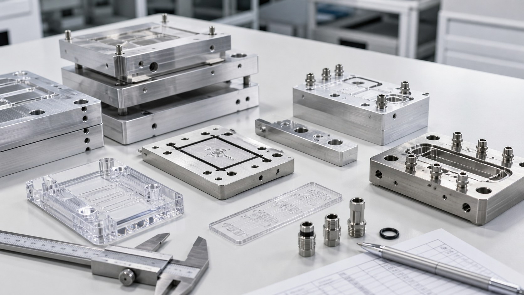
CNC Machining Microfluidic and Dialysis Manifolds: Port Geometry, Seal Lands and Clean Flow Paths
Why fluid-path manifolds need controlled machining
Microfluidic and dialysis subsystems depend on predictable flow paths, stable sealing surfaces and clean internal features. A CNC-machined manifold may route dialysate, buffer, reagent or calibration fluid through ports and channels that are too small to repair after assembly. Small errors at a port intersection, gasket groove or cover land can create dead volume, leakage, trapped residue or particle generation. The machining plan should therefore treat the part as a controlled fluid interface, not simply a block with holes.

Start with the flow architecture
Before quoting, trace the entire flow path from inlet to outlet and mark every blind end, cross-drilled passage, gasketed cover, valve seat and tube fitting. The drawing should define which surfaces are inside the wetted path and which are only mechanical supports. If the manifold interfaces with disposable tubing, dialysis cartridges, sensors or pumps, the device owner should provide the mating geometry and allowable dead-volume assumptions.
Material selection
PEEK is often considered for manifolds because it can combine machinability, chemical resistance and dimensional stability, but the final material must be approved by the device manufacturer. 316L stainless, PPSU or other polymers may be suitable in different designs. The RFQ should specify grade, certificate needs, color requirements, sterilization or cleaning exposure, and any restrictions on regrind, fillers or surface treatment.
Seal lands and gasket grooves
A gasket or O-ring groove must be controlled for width, depth, corner radius, flatness and surface finish. The screw pattern, cover stiffness and groove position all influence compression. A groove that is slightly too shallow can over-compress the gasket; one that is too deep may fail to seal. The drawing should distinguish a protective edge break from a functional sealing wall that must not be rounded.
Port intersections and burr control
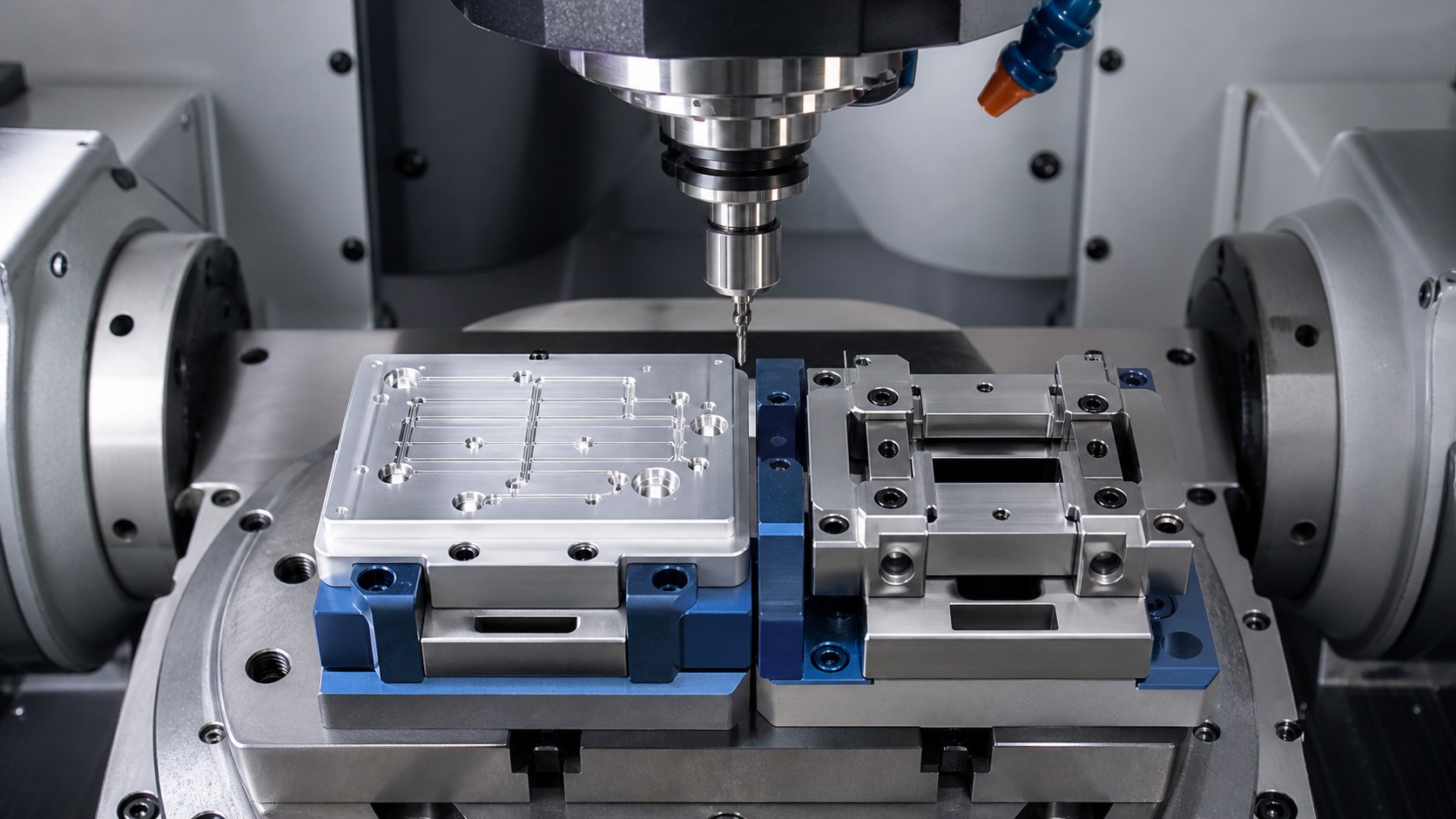
Intersecting micro ports are difficult because a burr can remain hidden inside the flow path. Tool sequence, drill geometry, breakthrough direction and chip evacuation should be planned before production. Secondary deburring must remove loose material without enlarging calibrated ports or rounding valve seats. Borescope or optical inspection may be required when direct viewing is not possible.
Fixturing and process stability
Polymer manifolds need gentle but repeatable fixturing. Excess clamp force can distort a sealing face, while heat from cutting may affect small features. Balanced roughing, sharp tools, stable datum transfer and controlled final passes help maintain flatness and port position. Parts should be measured after unclamping so temporary fixture distortion does not hide a problem.
Inspection strategy
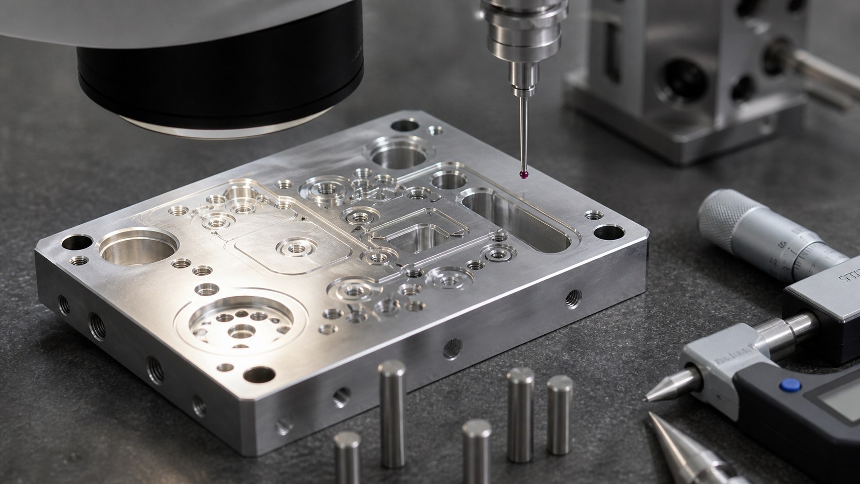
A first-article report can include port position, bore diameter, groove depth, flatness of seal lands, cover interface profile, thread quality and visual evidence for difficult intersections. Optical measurement may be better for tiny grooves, while CMM or dedicated fixtures capture datum relationships. Results should stay linked to material lot, program revision, fixture revision and cleaning batch.
Clean packaging and traceability
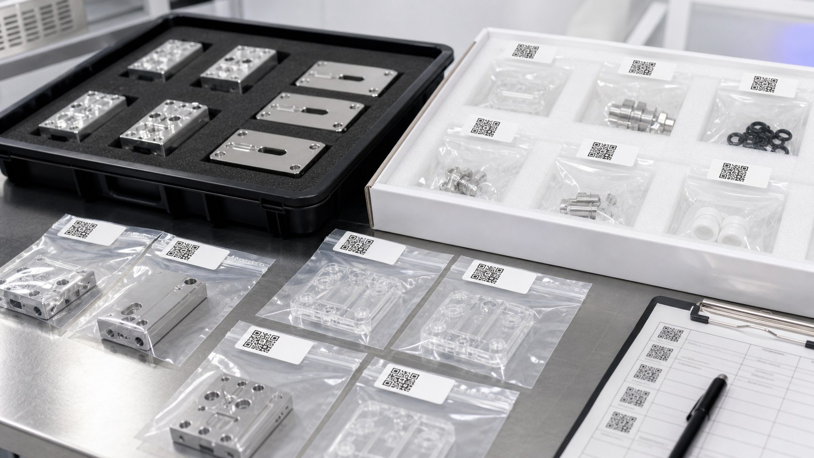
After machining, remove chips, coolant, polymer fines and loose debris from every port, channel and blind pocket. Packaging should keep seal lands and port openings from rubbing or collecting dust. Labels should identify part number, revision, lot and inspection status. Do not describe packaging as sterile unless a validated sterile process is included in the order.
RFQ handoff
A complete RFQ includes drawings, 3D models, flow-path notes, material specification, gasket details, fitting standards, critical dimensions, prototype and production quantities, cleanliness level, inspection records and leak-test method if required. The device manufacturer defines fluid compatibility and performance validation; machining records support that work but do not replace it.
FAQ
Can a machined manifold prove fluid performance?
No. Machining controls geometry and cleanliness; the device manufacturer validates flow, pressure, chemistry, sensors and system performance.
Why is PEEK used for some manifolds?
PEEK can offer useful machinability, stability and chemical resistance, but the exact grade and suitability must be approved for the device.
Which features are usually critical?
Port location, bore diameter, gasket groove depth, seal-land flatness, fitting threads, valve seats and hidden intersections are commonly important.
How are hidden burrs checked?
Use controlled machining, targeted deburring, optical or borescope inspection and cleaning methods matched to the port geometry.
Who defines leak-test limits?
The device owner defines pressure, medium, dwell time, connected ports, assembly state and acceptance criteria.
What should be in the RFQ?
Send drawings, models, material, gasket and fitting data, quantities, tolerances, cleaning requirements, inspection records and test protocol.