
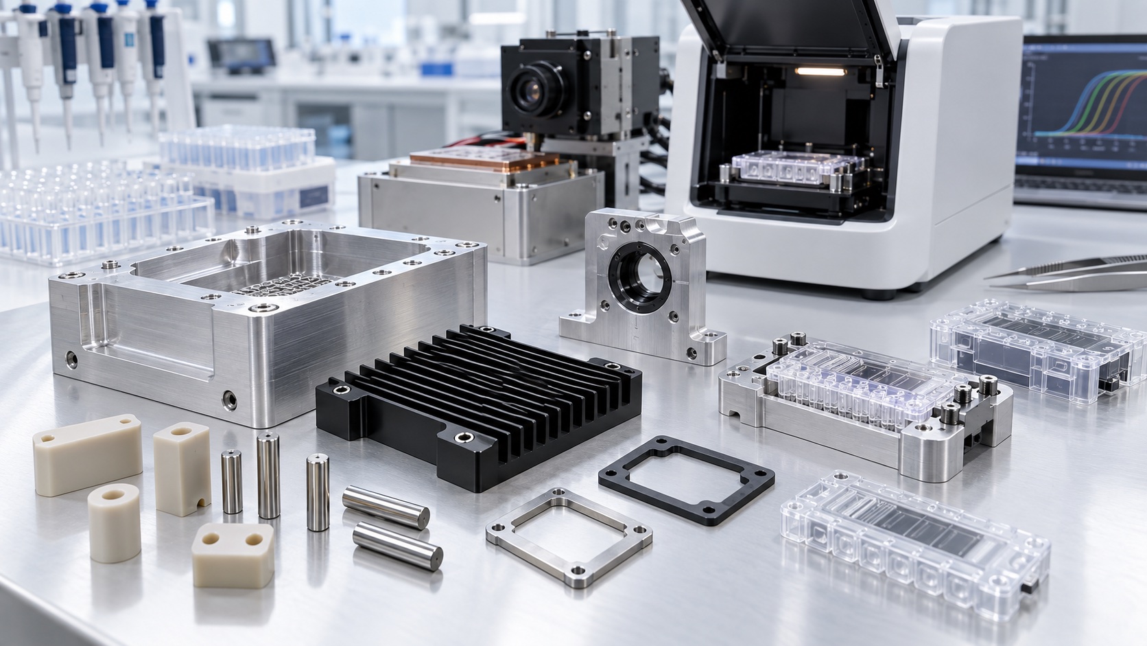
CNC Machining PCR Thermal-Cycler Sample Blocks: Well Geometry, Flatness and Thermal Repeatability
Why the sample block matters
PCR and point-of-care diagnostic instruments depend on controlled heating and cooling of tubes, strips or cartridges. The machined sample block does not create assay performance by itself, but its well geometry, contact surfaces and mounting references strongly influence how the complete instrument transfers heat. Variation in well depth, taper, wall thickness or base flatness can produce uneven contact and make calibration less repeatable. For that reason, the block should be treated as a thermal-mechanical interface with a controlled drawing, not as an ordinary pocketed aluminum plate.

Define the consumable interface
Start by identifying the actual tube, strip, microplate or disposable cartridge used by the device. The drawing should define well diameter, depth, taper, pitch and permitted edge condition together with the insertion and removal requirements. A nominal array pitch is not enough if individual wells can drift relative to the optical reader or heated lid. The equipment manufacturer should also define which surfaces contact the consumable, which areas are only clearance, and whether the carrier is exchanged by an operator or remains fixed inside the instrument.
Material and surface strategy
Aluminum alloys such as 6061-T6 are often considered because they machine predictably, keep mass manageable and conduct heat well. The final alloy, temper and surface finish remain design decisions for the equipment manufacturer. Anodizing, electroless nickel or another coating may improve wear or corrosion behavior, but coating thickness can alter small wells and fitted mounting features. The drawing should state whether dimensions apply before or after finishing, which surfaces are masked, and what color or cosmetic variation is acceptable without implying a thermal property that has not been validated.
Build a functional datum system
A useful datum chain normally begins with the heater or cooler mounting face, followed by two accessible locating edges or pin features. The well array, temperature-sensor pocket, fastener pattern and optical reference features should be located from that same functional system. Referencing only an outside cosmetic contour can hide a shift between the wells and the instrument. The datum scheme should work for CNC setup, coordinate measurement and final assembly so that the same relationships are controlled throughout manufacturing.
Machining sequence and distortion control
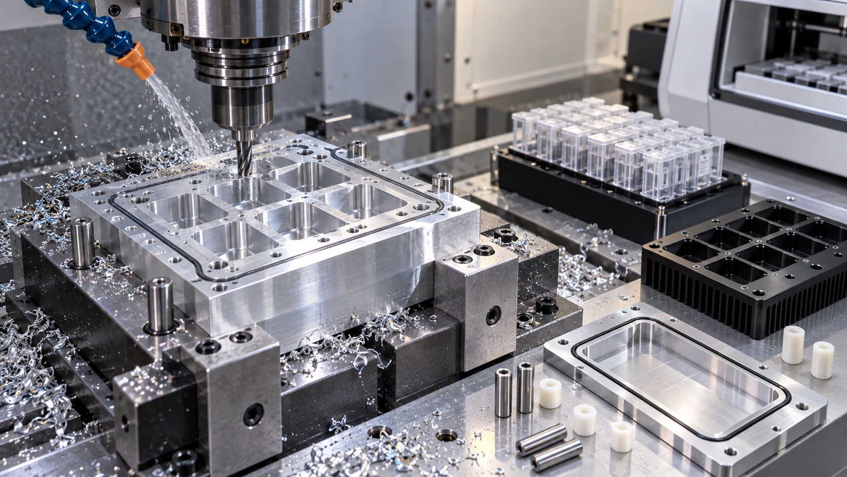
The process typically roughs both sides in balanced stages, establishes the mounting face, then machines the well array and sensor features from stable references. A thin plate with many deep wells can move as residual stress is released, so stock condition, clamping force and removal sequence matter. Wells may require dedicated drills, reamers, form tools or multi-axis interpolation depending on the geometry. Finish passes should occur after the major material removal, and the part should be checked after unclamping because fixture pressure can temporarily conceal flatness error.
Control the well array
Each well is part of a pattern, so inspection must consider both local geometry and accumulated position. Diameter, taper, depth, bottom shape, pitch and row-to-row alignment may all affect contact with the consumable. Tool wear can gradually change the wells across a batch, while chips trapped in a deep feature can mark the surface or break a cutter. A defined tool-life rule, in-process checks and a stable probing strategy help prevent the final rows of an array from drifting away from the first rows.
Flatness, sensor pockets and assembly
The mounting face, heater interface and temperature-sensor pocket should be controlled as a related group. Excessive flatness error can create uneven clamping or thermal interface gaps, while a misplaced sensor pocket may no longer represent the intended thermal zone. Screw patterns and locating pins also influence contact pressure. Inspection should record the free-state condition unless the drawing explicitly defines a restrained measurement. Mating heaters, films, pads or sensors should be included in the design review even when the machining supplier only delivers the metal component.
Inspection, cleaning and documentation
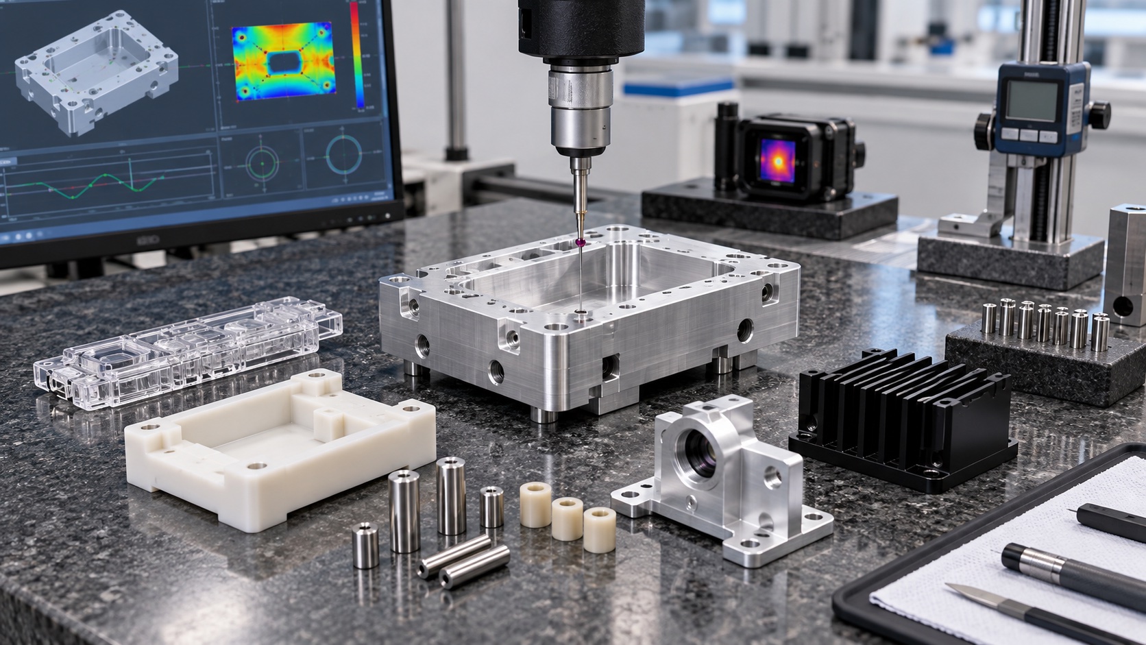
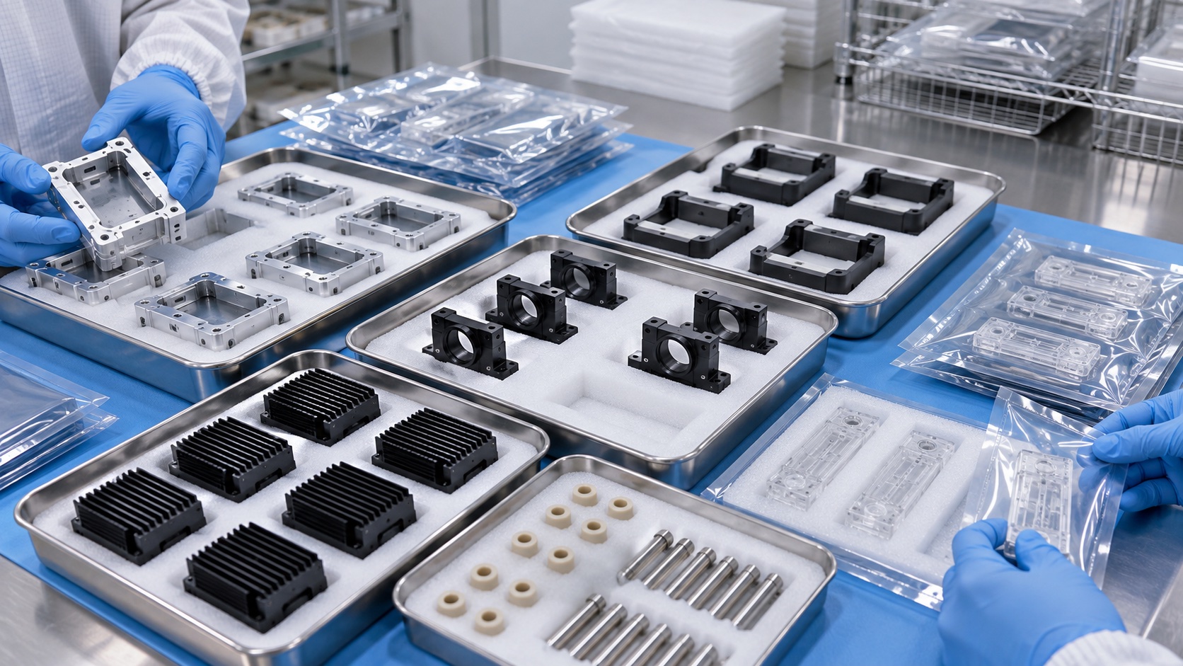
A first-article plan can combine CMM inspection for array location, dedicated gauges or optical methods for well geometry, and surface checks for the mounting face. Critical results should remain linked to material lot, program revision, fixture revision and coating batch. After machining and finishing, remove chips, coolant, polishing residue and loose particles from every well and blind pocket. Protective trays or individual packaging should prevent wells and flat interfaces from rubbing during transport. Packaging must not be described as sterile unless a validated sterile process is explicitly included.
A complete RFQ package
A useful RFQ contains the 2D drawing, matching 3D model, consumable interface definition, alloy and finish, dimensions that apply after coating, critical datum relationships, prototype and production quantities, cleanliness requirement, inspection plan and documentation expectations. If thermal mapping, cycle testing or assembly testing is required, the device owner should define the fixture, sensors, temperature range, cycle count and acceptance limits. Machining records support the manufacturer's validation but do not replace assay, instrument or regulatory validation.
FAQ
Can a machined sample block guarantee PCR accuracy?
No. It provides controlled mechanical and thermal interfaces, while the device manufacturer validates heaters, sensors, control software, consumables and assay performance as a complete system.
Which well dimensions are usually critical?
Diameter, taper, depth, bottom form, pitch and position relative to the mounting and optical datums are commonly important, subject to the released drawing.
Why must coating thickness be planned?
Anodizing or plating can reduce well diameter and alter fitted features. The drawing should define masking and whether dimensions apply before or after finishing.
How is flatness checked?
The inspection plan should define the datum, support condition, measurement method and whether the part is evaluated free or restrained.
Who defines thermal-cycle acceptance limits?
The PCR or POCT equipment manufacturer defines the temperature range, sensor arrangement, fixture, cycle count and acceptance criteria.
What should accompany an RFQ?
Send drawings, models, consumable details, material and finish requirements, quantities, critical tolerances, cleanliness level and required inspection or test records.