
CNC Machining Anesthesia Workstation Flow-Sensor Housings: Bore Alignment, Sealing and Cleanliness
Why the flow-sensor housing matters
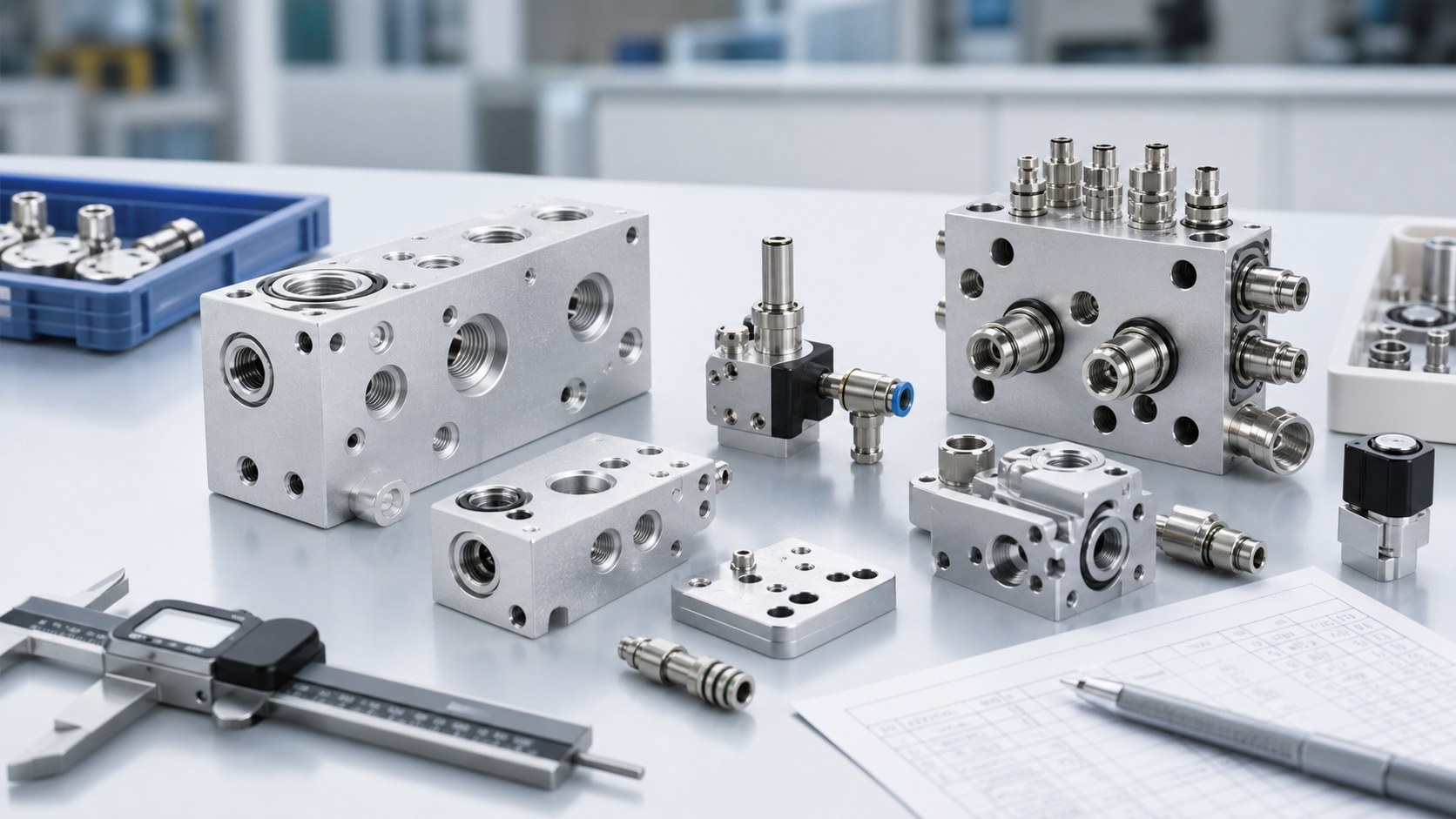
An anesthesia workstation depends on stable gas delivery, monitored flow and reliable mechanical interfaces between valves, sensors, manifolds and breathing-circuit connections. A machined flow-sensor housing does not determine clinical performance by itself, but it holds the sensor bore, sealing features and mounting references that allow the instrument manufacturer to calibrate the complete pneumatic path. If a bore shifts, a gasket land is scratched or a hidden burr remains near the gas passage, assembly can lose repeatability. The machining supplier therefore needs to treat this part as a functional gas-path component rather than a simple enclosure.

Define the gas-path boundary first
Before selecting cutters or fixtures, review which features are actually inside the gas path. Identify inlet and outlet passages, sensor windows, pressure tap locations, purge or sampling ports, O-ring grooves and cover interfaces. Some surfaces may only locate electronics or protective covers, while others directly influence sealing and calibration. The device manufacturer should define the functional boundary, acceptable materials, cleaning level and any test state. This prevents the shop from applying a generic housing approach to a component that needs controlled bore geometry and residue management.
Material and finish considerations
6061-T6 aluminum is often considered for compact respiratory and anesthesia components because it machines cleanly, keeps weight low and can be anodized for protection. The final material selection belongs to the device designer and must account for gas exposure, cleaning agents, coating, grounding needs and compatibility with seals. Stainless steel or engineering polymer may be selected for different requirements. Whatever the choice, material certificates, lot identity, coating condition and dimensions before or after finishing should be explicit, because a fitted bore or sensor pocket can change if coating thickness is not planned.
Build a datum chain around the bore
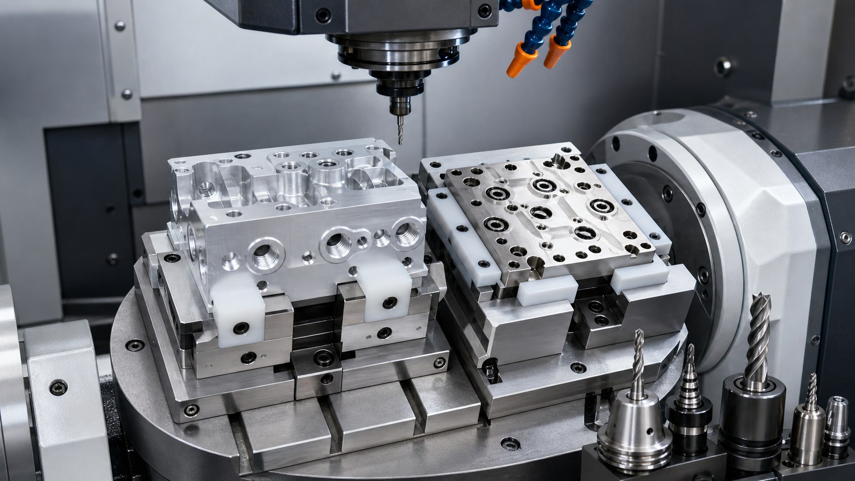
The sensor bore and adjacent sealing features should be dimensioned from a functional datum system that can also be used by CNC fixtures, inspection equipment and assembly gauges. A common approach is to establish the mounting face, a long side datum and a secondary stop, then locate the bore, pressure taps and fastener pattern from that system. Cosmetic outside profiles should not become the only reference. If the sensor module uses dowels or precision screws, their positions must be controlled together with the bore rather than checked as unrelated holes.
Machining sequence for stability
A stable sequence roughs the blank, establishes the primary datums, opens the main flow passage and leaves sealing lands for controlled finish cuts. Thin walls around a sensor window or port boss can move when the part is unclamped, so intermediate checks and balanced stock removal may be needed. Deep bores require chip evacuation and tool-wear control, especially where cross-holes break into the passage. Final passes on the bore, groove and gasket face should happen after the part is mechanically stable, with enough access for later inspection.
Sealing surfaces and burr control
The O-ring groove, cover land, thread entrances and cross-drilled intersections deserve separate acceptance criteria. Removing burrs is not the same as rounding every functional edge. A raised lip at a sensor bore can disturb assembly, while over-polishing a sealing land can change compression or flatness. Deburring should follow a defined process using suitable tools, magnification and, where needed, borescope inspection. The drawing should identify which edges are gas-contact edges and which edges are only handling breaks, because they carry different risks.
Inspection and customer-defined testing
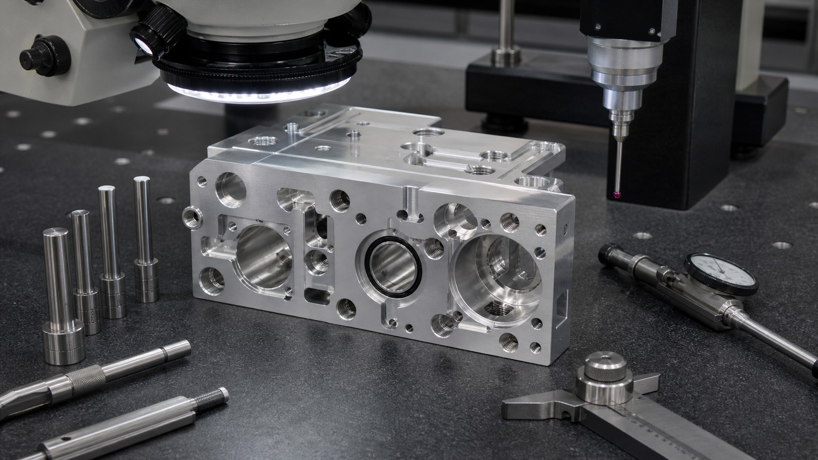
Dimensional inspection normally covers bore diameter and position, coaxiality or perpendicularity where specified, groove width and depth, face flatness, port locations, thread quality and critical surface finish. A CMM can verify geometric relationships, while optical inspection helps confirm small edges and surface defects. Leak or flow testing can be useful, but pressure, medium, dwell time, port plugging and acceptance limits must come from the anesthesia device specification. A machine shop should not invent clinical test values; it should provide the fixture discipline and records requested by the device owner.
Cleaning, packaging and RFQ handoff
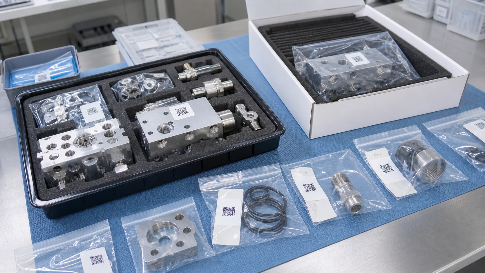
After machining, finishing and inspection, the part should be cleaned to remove coolant, chips, abrasive residue and loose particles from passages and pockets. Protective packaging should keep bores, gasket faces and threaded ports from rubbing against other parts. Labels can include part number, revision, material lot and inspection status without claiming sterility unless a validated sterile supply chain is part of the order. A useful RFQ includes 2D drawings, 3D models, material and finish requirements, seal details, critical features, quantities, cleaning level, test protocol and required documentation.
FAQ
Can a machined flow-sensor housing guarantee anesthesia system accuracy?
No. The housing provides mechanical references and gas-path geometry; the device manufacturer validates the complete sensor, electronics, software and pneumatic system.
Which features are usually critical?
The sensor bore, pressure or sampling ports, O-ring grooves, cover lands, datum faces, dowel holes, thread entrances and gas-contact edges commonly need special control.
Why is coating planning important?
Anodizing or other finishes can change fitted bores and sealing interfaces. The drawing should state which dimensions apply before or after finishing and what must be masked.
How are hidden gas-path burrs checked?
A controlled deburring sequence is followed by optical inspection, borescope inspection or another approved method for cross-holes and inaccessible intersections.
Who defines leak or flow-test limits?
The anesthesia equipment manufacturer defines the medium, pressure, dwell time, plugged ports, assembly state and pass/fail criteria.
What should be included in an RFQ?
Send drawings, models, material and finish needs, seal details, critical tolerances, production quantities, cleanliness requirements, test protocol and documentation expectations.