
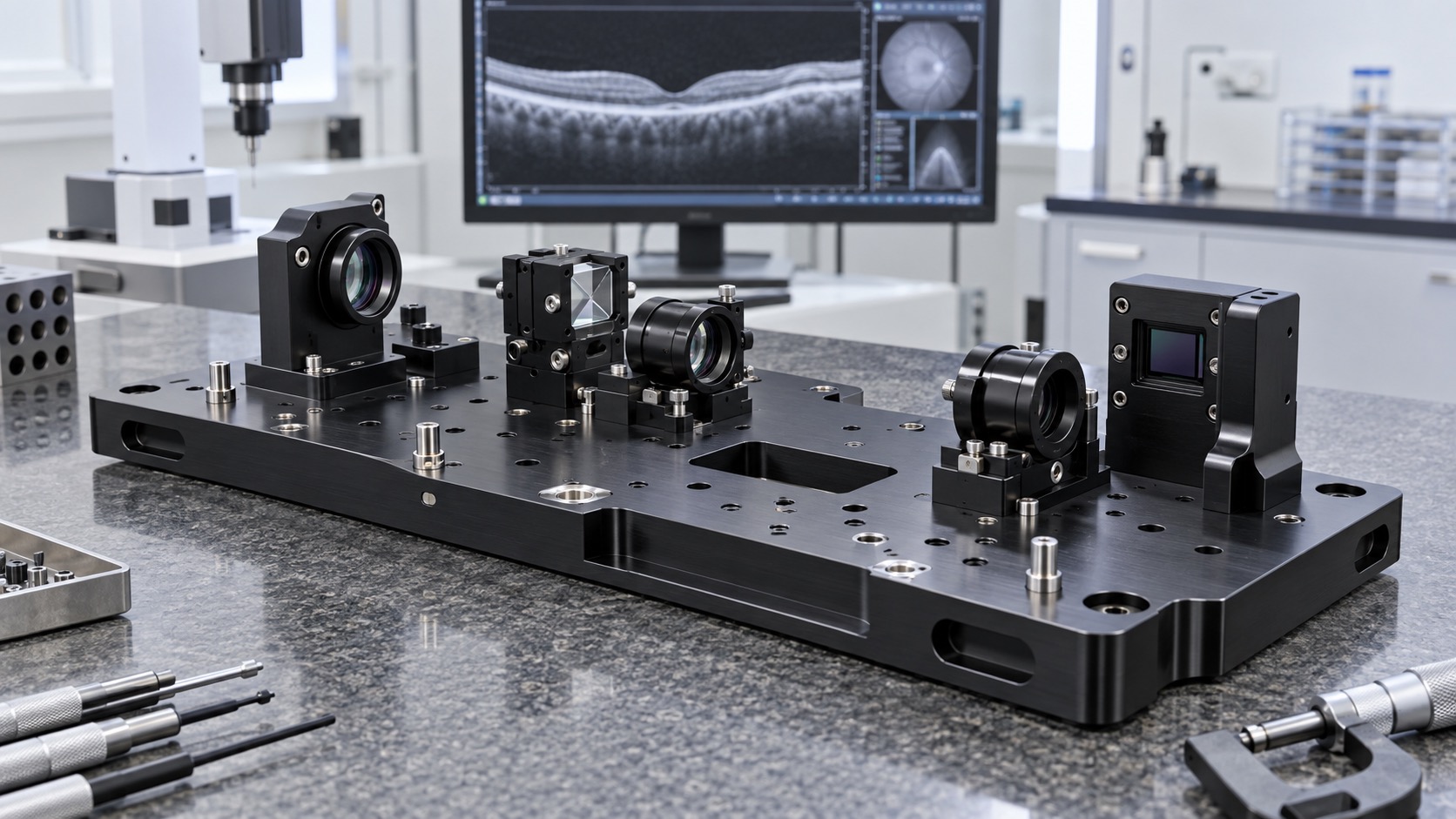
CNC Machining Ophthalmic OCT Optical Platforms: Thermal Stability, Datums and Alignment
Why the optical platform matters
An ophthalmic optical coherence tomography system builds a retinal image from tightly controlled optical paths, scanners, detectors and reference components. The machined base plate does not create the image, but it fixes the relative positions of those modules and provides a stable mechanical reference during transport, calibration and service. Small changes in flatness, hole position or mounting height can consume alignment range. The equipment manufacturer remains responsible for optical performance, electrical safety, calibration and clinical validation; the machining supplier is responsible for making the released mechanical interfaces repeatably.

Map the complete alignment chain
Drawing review should start with the optical chain rather than individual dimensions. Identify which surfaces support the light source, galvanometer or MEMS scanner, beam splitter, reference arm, detector and patient-side optics. Mark the primary mounting plane, two clocking references and the dowel or pilot features that locate each module. Adjustable slots need a defined travel direction and enough clearance for alignment without weakening the plate. Mating CAD, hardware models and an assembly sequence reveal tool access and clashes before the first fixture is built.
Choose material with thermal behavior in mind
6061-T6 aluminum is often considered for an optical platform because it combines low mass, machinability and useful thermal conductivity. The final choice must account for stiffness, temperature range, cleaning agents, coating and the expansion behavior of steel pins, optical mounts and sensor housings. Material certificates and stock condition should be specified. A stable platform also depends on thickness distribution and mounting constraints; changing alloy or removing a large pocket can alter thermal drift even when every room-temperature dimension still passes inspection.
Build a functional datum scheme
A practical datum scheme begins with the equipment mounting plane, adds a long side or precision edge for clocking, and uses a tertiary feature to stop translation. Critical dowel bores, lens-mount pilots and detector interfaces should be dimensioned from this shared system. Cosmetic outer contours should not become the only reference for optical alignment. The same datums should be accessible to CNC fixtures, coordinate measurement and assembly gauges. Where the platform mounts on isolators, inspection should distinguish free-state flatness from the condition created by installation torque.
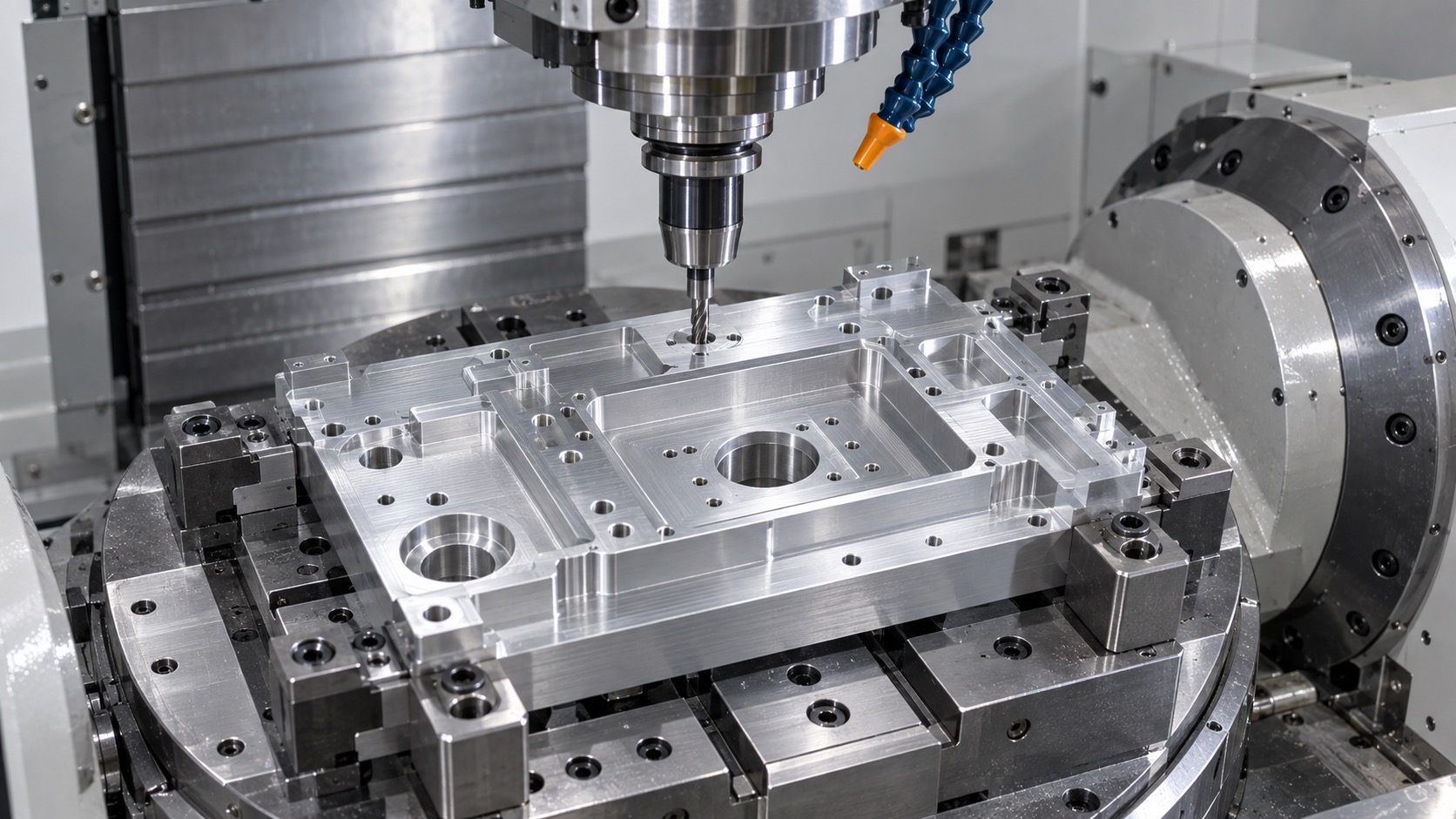
Control stress and deformation during machining
Optical plates commonly combine a broad thin section with deep pockets, islands, threaded grids and local bosses. Remove material in balanced stages, retain support near critical pads and allow stress to settle before the final face and hole operations. Clamps should act on rigid zones and avoid bending the plate against a fixture. Sharp tools and stable finishing passes limit heat and burrs. After unclamping, verify flatness and critical height relationships. If stress relief or an intermediate aging step is required, it belongs in the released process rather than being added after dimensions drift.
Machine holes, pilots and slots as one system
Precision dowel holes establish repeatable module location, while threaded holes provide clamp load and slots provide adjustment. Their relationship matters more than any feature in isolation. Pilot bores may be finished by boring or reaming after the mounting plane is established, with gauge method and temperature recorded. Thread depth must account for bottom clearance and anodize. Slot ends and counterbores need burr-free edges so a mount can move smoothly. Temporary protective plugs may keep coating out of fitted bores when the drawing requires a controlled final size.
Plan anodizing and conductive interfaces
Black anodizing can reduce stray reflections and protect aluminum, but it adds thickness and electrically isolates the surface. The drawing should identify fitted bores, grounding pads, thermal contacts and precision datum pads that require masking or post-finish control. Mask boundaries must not cross an optical seat or create a raised edge under a mount. The supplier should agree whether dimensions apply before or after coating and how cosmetic acceptance is judged. Uncontrolled hand scraping after anodizing can damage flatness, corrosion protection and traceability.
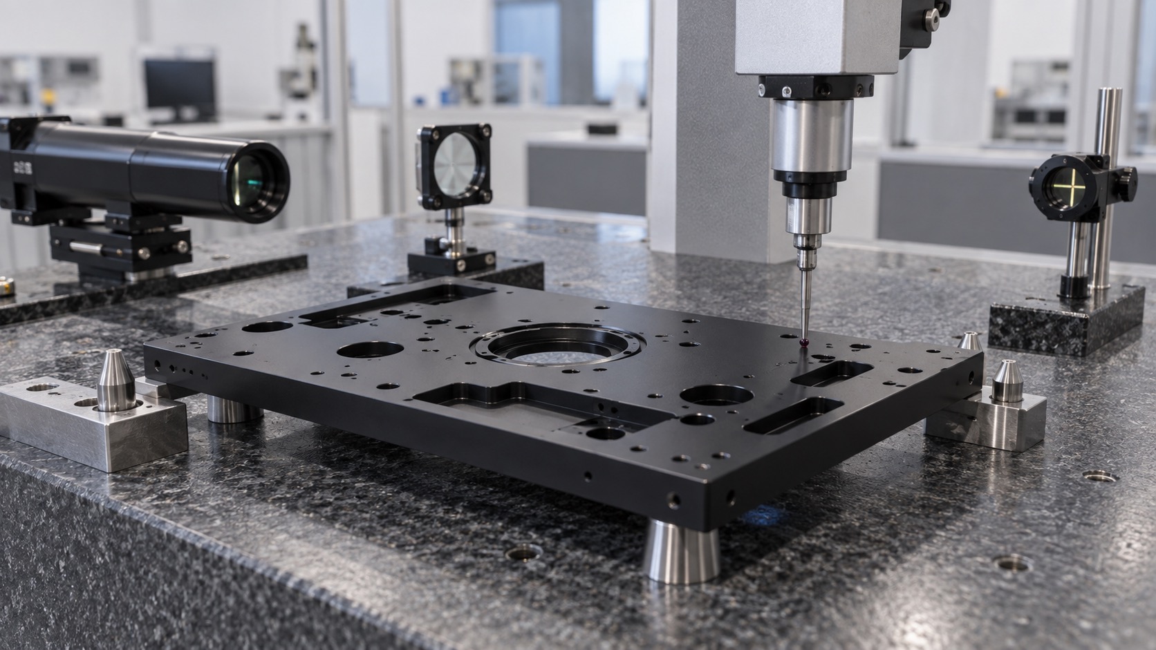
Inspect geometry that drives calibration
A first-article plan typically covers base flatness, local pad height, dowel-hole size and position, pilot concentricity, slot travel, thread quality and the relationship between detector and scanner mounting zones. CMM results should reference the drawing datums and state the support condition. Optical tools or an autocollimator may support angular checks when defined by the customer, while approved gauges can confirm module fit. Dimensional inspection supports assembly, but it does not replace the manufacturer's optical alignment, retinal-image calibration or environmental testing.
Clean, protect and prepare a useful RFQ
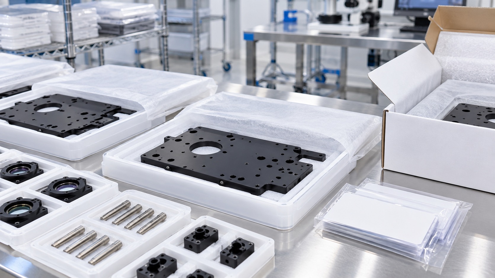
After anodizing and inspection, remove loose particles, coolant residue and chips from pockets, threads and fitted bores. Protect datum pads and precision holes with non-shedding materials, and separate optical mounts so they cannot scratch the platform. Packaging can be clean and traceable without being described as sterile. A useful RFQ includes released drawings and models, module interfaces, alloy and temper, finish and masking map, quantities, temperature assumptions, critical dimensions, inspection records, cleanliness level and any customer-supplied fit gauges.
FAQ
Can a machined base plate guarantee OCT image quality?
No. It provides mechanical references, while optical design, alignment, electronics, software, calibration and system validation determine image performance.
Which features usually control optical alignment?
The mounting plane, local datum pads, dowel-hole positions, pilot bores, scanner and detector interfaces, and adjustment-slot direction are common controls.
Why is 6061-T6 often considered?
It offers useful machinability, low mass and thermal conductivity, but the equipment designer must confirm stiffness, temperature, finish and compatibility requirements.
Should dowel holes be measured before or after anodizing?
The drawing should define the accepted condition. Fitted bores may require masking or a controlled post-finish process to preserve size and position.
Does CMM inspection replace optical calibration?
No. CMM data verifies mechanical geometry; the complete OCT instrument still requires optical alignment, calibration and environmental verification.
What should an RFQ include?
Provide drawings, models, module interfaces, material, coating and masking, quantities, critical tolerances, temperature assumptions, inspection and cleanliness requirements.