
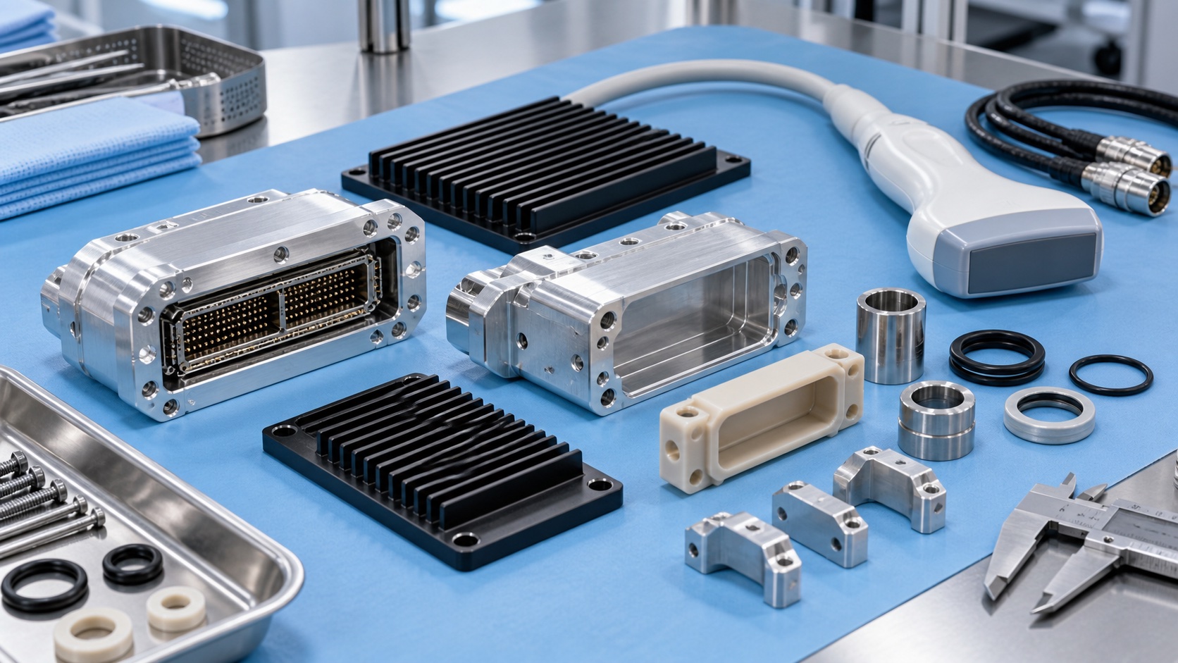
CNC Machining Ultrasound Probe Connector Housings: Alignment, Shielding, Sealing and Strain Relief
Why the connector housing is functional
A portable ultrasound probe connector housing does more than cover a cable termination. It locates a high-density electrical interface, supports latch loads, protects the cable transition and may contribute to shielding, sealing and heat transfer. Small errors in pin-window position, latch geometry or gasket compression can make assembly difficult or inconsistent. The machine shop manufactures the released mechanical component, but electrical safety, image quality, ingress protection and device performance remain responsibilities of the ultrasound equipment manufacturer and its validated assembly.

Map every interface before machining
The review should identify the equipment-side connector, probe cable, strain-relief boot, latch, gasket, shielding spring and PCB or termination support. Mark which surfaces locate the connector insert and which merely provide clearance. The drawing should show cable bend direction, mating travel and the reference plane used for insertion. If a conductive gasket or spring fingers contact the housing, their contact band needs a defined position and finish. Mating models or approved samples help expose clashes before tooling is released.
Choose material and finish together
6061-T6 aluminum is often considered for light, machinable connector shells that can be anodized, while stainless inserts may provide wear resistance at latches or fasteners. The final choice depends on strength, cleaning agents, electrical bonding, corrosion and cosmetic requirements. Anodizing can electrically isolate surfaces, so grounding and shielding contact zones may need masking or a conductive finish specified by the designer. Exact alloy, temper, finish and certificate requirements should be frozen before first-article production.
Build the datum scheme around mating
A reliable datum system starts with the connector-insert seat or mounting face, then uses side and clocking features to control the pin window, latch and outer shell. Cosmetic contours should not be the only reference for high-density connector alignment. The same datums should remain accessible in CNC setups, CMM inspection and assembly gauging. If two shell halves form the opening, their split-line relationship and fastener preload must be included in the tolerance analysis rather than inspecting each half as an unrelated part.
Control thin walls and pockets
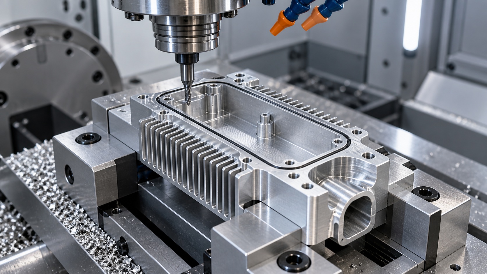
Connector housings often combine deep cavities, thin walls, ribs and small threaded bosses. Roughing removes material in balanced stages and leaves support around the insert seat and latch area. Fixtures should distribute clamping force across rigid zones and avoid marking cosmetic or sealing surfaces. Sharp tools and controlled entry reduce burrs near cable and gasket features. Final passes on the insert seat, latch stop and sealing land should occur after major stress has been released, followed by inspection in the unclamped state.
Protect shielding and sealing paths
A shielding path needs continuous, predictable contact rather than a surface that is merely metallic in appearance. The drawing should identify masked conductive bands, acceptable coating boundaries and fastener interfaces. Likewise, a gasket groove depends on width, depth, corner radius and land flatness defined by the equipment designer. Burrs, coating buildup or split-line steps can interrupt either path. Machining evidence can confirm geometry and surface condition, but EMC and ingress performance must be tested on the completed device with final hardware and assembly process.
Machine strain-relief features carefully
Cable exits and boot interfaces carry repeated bending and pull loads. The housing should provide the specified seat, anti-rotation feature and generous edge condition without pinching the cable. Threads and clamp features must remain clear of the cable envelope. If overmolding or adhesive is used, the designer should define bond surfaces and prohibited coating areas. A smooth visible radius is not proof of cable durability; bend-life and pull testing belong to the assembled probe and approved cable process.
Inspect the assembly-driving features
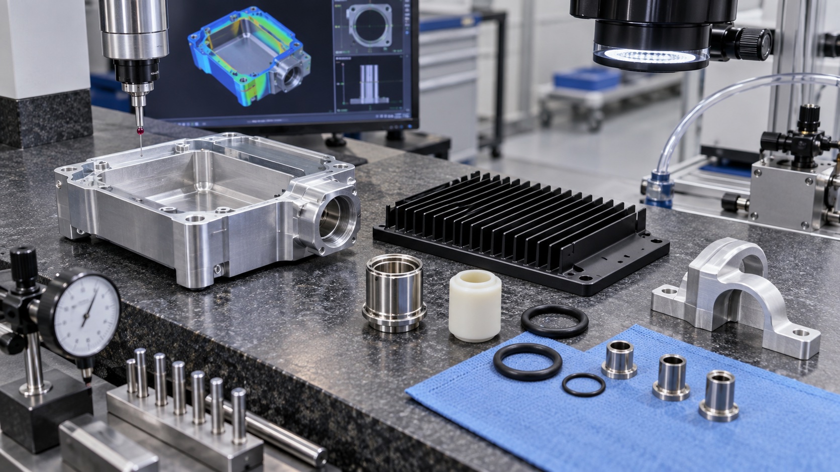
Inspection normally covers insert-seat position, pin-window profile, latch stop, screw-boss location, gasket groove, split-line flatness, cable-exit geometry and masked conductive zones. CMM and optical tools verify relationships, while thread gauges and approved mating fixtures support fit checks. Record drawing revision, finish condition, measurement fixture and material lot. A first-article report should distinguish dimensions measured before finish from those accepted after anodizing or other treatment.
Clean, package and quote clearly
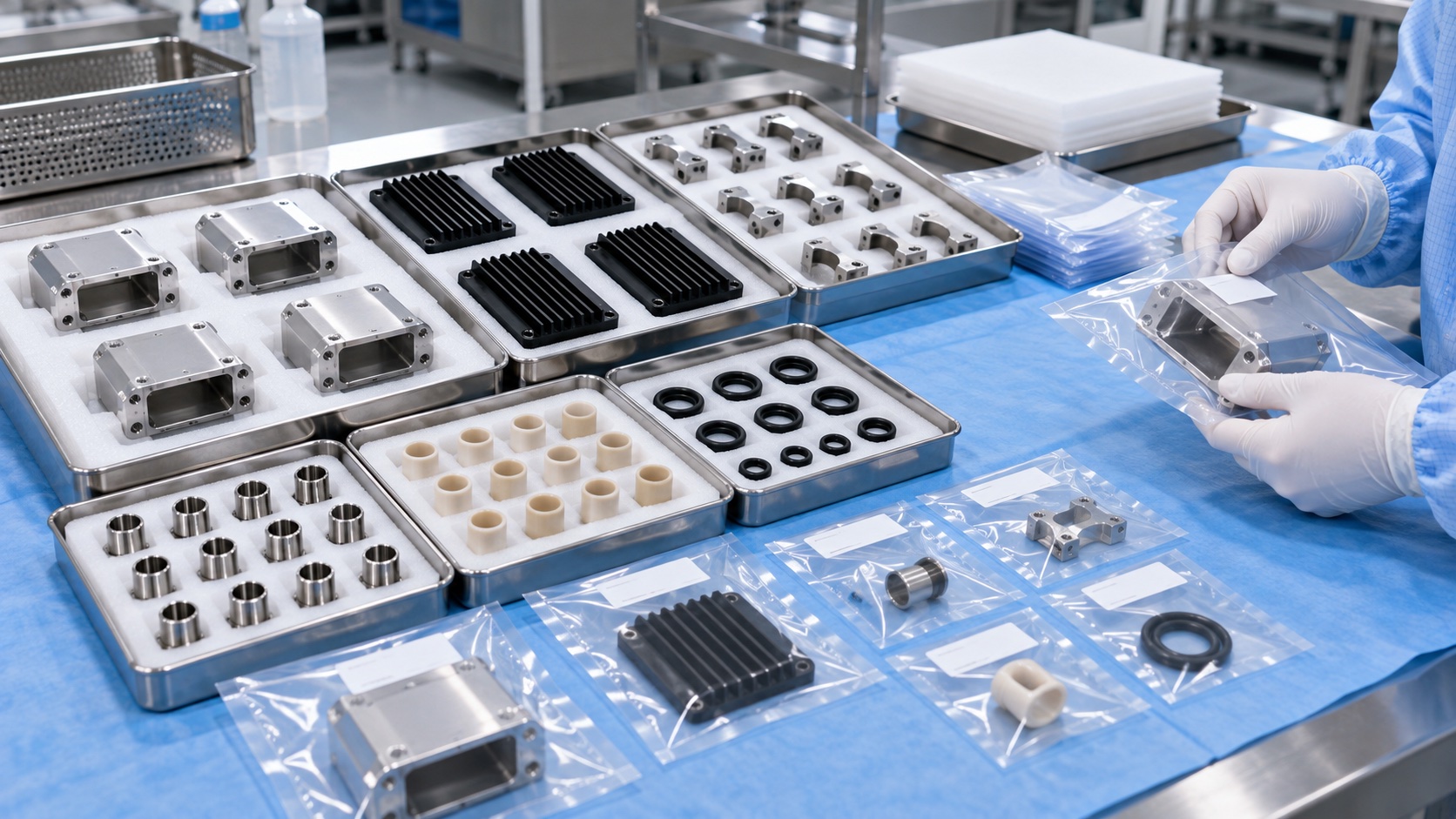
After machining and finishing, remove chips, abrasive residue and loose coating particles from cavities and threads. Protect the insert seat, gasket land and conductive bands from rubbing during transport. Packaging may be clean and traceable without being sterile. A complete RFQ includes models, drawings, material and finish, masking map, connector and boot interfaces, quantities, critical tolerances, inspection records, cleanliness level and customer-supplied mating parts. Clear inputs reduce late rework and unsupported assumptions.
FAQ
Can the housing alone guarantee ultrasound image quality?
No. Image quality depends on the transducer, electronics, cable, connector, software and system validation. The housing supports mechanical alignment and protection.
Which dimensions usually control connector alignment?
Insert-seat position, pin-window profile, mounting face, clocking feature, latch stop and shell split-line relationship are common controls.
Why are some anodized areas masked?
Shielding, grounding, close fits and thread interfaces may require conductive or dimensionally controlled surfaces defined by the device designer.
Does a correct gasket groove prove ingress protection?
No. The final gasket, fasteners, torque, shell halves and test method determine assembled ingress performance.
How is strain relief inspected?
Seat geometry, anti-rotation details and cable clearance are inspected mechanically; bend-life and pull tests are performed on the assembled cable system.
What belongs in a useful RFQ?
Send drawings, models, alloy, finish and masking, mating connector and boot data, quantities, tolerances, inspection and cleanliness requirements.