
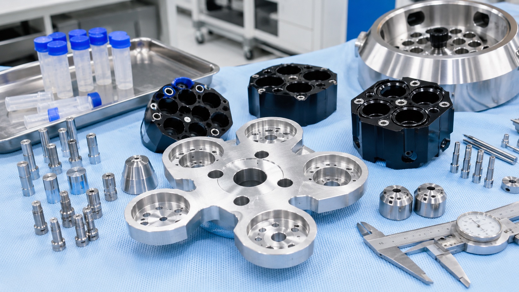
CNC Machining Medical Centrifuge Rotor Interfaces: Runout, Mass Symmetry and Balance Control
Why the rotor interface matters
A medical centrifuge converts motor speed into controlled sample separation. The machined interfaces between spindle, hub, adapter and sample carrier determine how consistently the rotating assembly sits on its axis. Small errors in bore position, mounting-face flatness or mass distribution can increase vibration and bearing load. The component supplier should manufacture to the released drawing and provide dimensional evidence, but cannot set a universal safe speed or certify the completed rotor. Maximum speed, fatigue life, containment and dynamic-balance limits belong to the centrifuge manufacturer's validated system design.

Begin with the load path
Before planning tools, trace the load path from the motor shaft through the hub to the buckets, tubes or sample carriers. Identify which face transmits clamp load, which diameter centers the assembly and which key, pin or fastener transmits torque. The drawing should separate locating features from retention features. It should also state the operating orientation, intended speed range, maximum assembled mass and any customer-controlled preload. This information lets the machine shop understand why certain relationships are critical without inventing performance limits.
Choose and document material
High-strength aluminum such as 7075-T6 may be considered for a lightweight rotor adapter, while stainless steel may suit smaller wear or attachment features. Final material selection depends on stress analysis, cleaning chemistry, corrosion exposure, fatigue and equipment regulations. The exact alloy, temper, stock form and certificate requirement must be specified. Keep material heat or lot identity with every traveler. Substitution between tempers or stock conditions is not a minor purchasing change because strength, residual stress and machining movement can differ.
Build the datum structure around rotation
A useful datum scheme starts with the mounting face and central pilot or bore, then clocks the hole pattern from a defined secondary feature. The bore axis, face flatness and bolt-circle position should be measurable in the same coordinate system. If both sides of the adapter contain functional features, minimize datum transfers or provide stable inspection pads. Concentricity should be expressed with appropriate geometric tolerances rather than vague notes. The design team should also identify whether the part is balanced individually or only as part of the final rotor assembly.

Machine symmetrically
Removing material unevenly from a plate or forging can release stress and move the bore or face. A stable sequence roughs both sides, leaves finishing stock, allows the blank to stabilize and then finishes the pilot, mounting face and pattern from controlled setups. Clamping force must not dish a thin adapter. Tool paths should preserve repeated pocket geometry and avoid local overcut that changes mass. When serial numbers or balance correction features are required, their location and allowable depth must be controlled so identification does not become an uncontrolled mass change.
Control bores, threads and pockets
The central pilot and mating bore normally govern radial location. Measure size, roundness and relationship to the mounting face. Bolt holes and threads need position, engagement and edge-distance review because unequal clamp load can distort the interface. Repeated pockets or sample-carrier seats should be machined with common tools and consistent edge treatment. Burrs around holes can prevent full seating, while aggressive deburring can remove unequal amounts of material. A defined edge standard makes both assembly and mass symmetry more repeatable.
Separate dimensional inspection from balancing
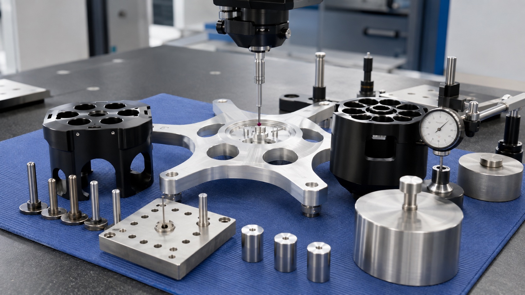
CMM inspection can verify face flatness, pilot location, bolt-circle position, pocket depth and geometric relationships. Runout can be checked on a defined mandrel or customer-approved fixture. Mass can be recorded with a calibrated scale. Dynamic balancing, however, depends on the specified assembly state, speed, correction planes and residual-unbalance limit. Those values must come from the centrifuge manufacturer. A part that passes dimensions may still require assembly balancing, while balance data does not replace inspection for cracks, wrong material or damaged threads.
Manage finish and cleanliness
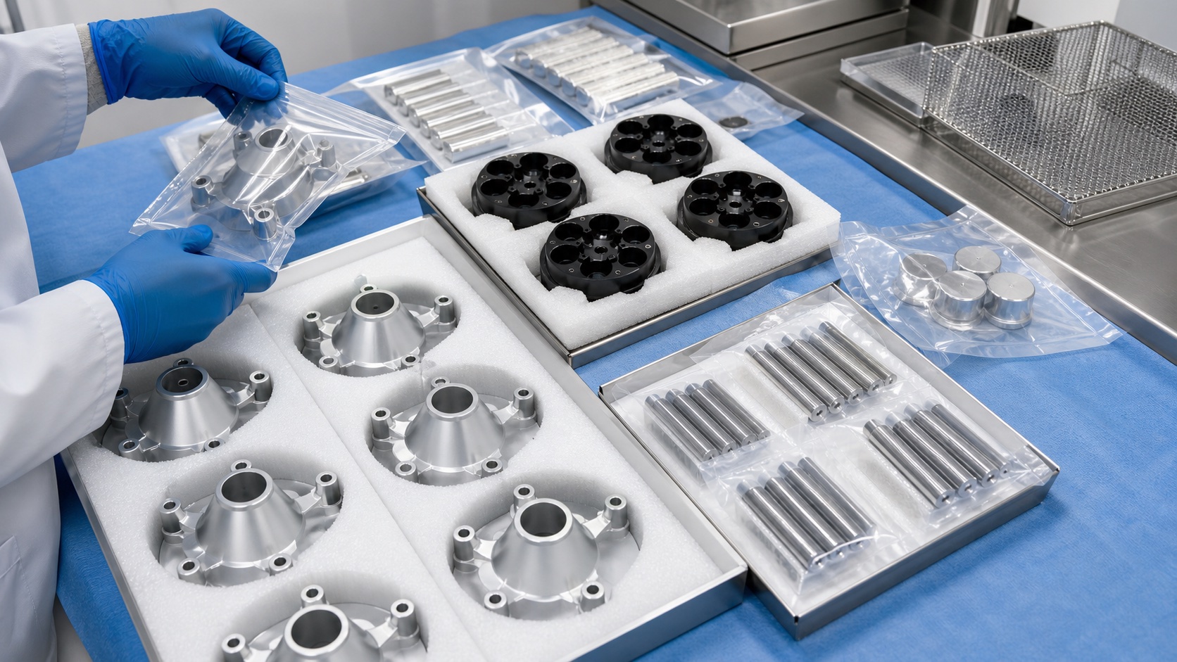
Anodizing or another protective finish can improve corrosion and handling resistance, but coating buildup affects pilots, threaded holes and contact faces. The drawing should define masked areas and dimensions that apply after finishing. Avoid finish damage at high-load interfaces and inspect for dents or scratches before packaging. Cleaning removes chips, abrasive residue and loose coating particles from pockets and threaded holes. Packaging should separate finished parts and protect the bore and mounting face; it should be described as clean and traceable rather than sterile unless a validated sterile process is explicitly included.
Prepare an effective RFQ
A complete RFQ provides 2D and 3D data, material and temper, prototype and annual quantities, operating envelope supplied by the device team, critical datums, finish, inspection plan and documentation needs. Include the mating spindle or gauge definition, insert and fastener specifications, balance responsibility and any approved correction zones. State whether serial marking, first-article inspection, material certificates and finish records are required. Clear inputs let the supplier quote machining, fixtures, metrology and traceability without making assumptions about centrifuge safety.
FAQ
Can CNC machining alone guarantee safe centrifuge speed?
No. Safe speed and rotor life require system-level stress, fatigue, containment and balance validation by the centrifuge manufacturer.
Which features usually control runout?
The mounting face, central pilot or bore, spindle interface and their geometric relationship are typical runout-driving features.
Why is symmetric machining important?
Balanced stock removal reduces movement from residual stress and helps repeated pockets retain consistent geometry and mass.
Does a dimensional report replace dynamic balancing?
No. Dimensional inspection and balancing measure different risks. Balance conditions must define assembly state, speed, planes and acceptance limit.
How should anodizing be handled?
Specify masking and post-finish dimensions for pilots, contact faces, threads and other close interfaces, then inspect those features after finishing.
What should be included in the RFQ?
Send drawings, models, alloy and temper, quantities, datums, operating requirements, finish, inspection, balance responsibility and traceability needs.