
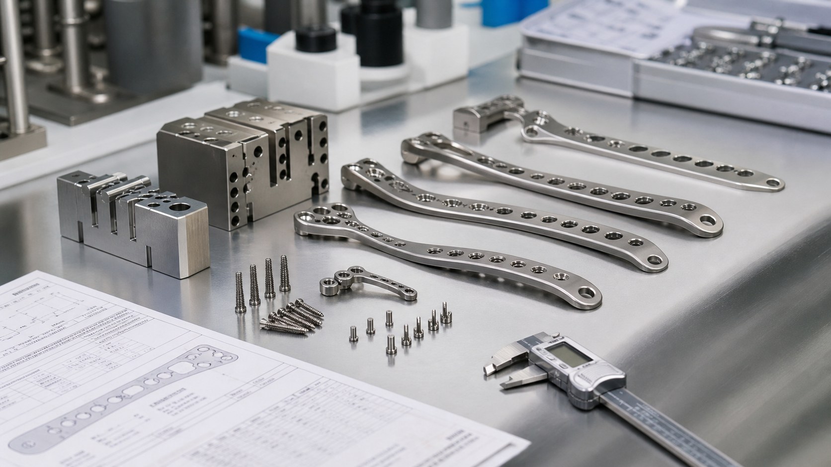
CNC Machining Orthopedic Guide Interfaces: Drill-Axis, Thread and Datum Control
A guide is an assembly, not a single hole
An orthopedic guide may bring a drill sleeve, a supporting frame, a locking clamp and a mating instrument into one controlled relationship. Its mechanical purpose is to locate the tool path defined by the device designer while remaining practical to assemble and inspect. A bore that measures correctly by itself may still point in the wrong direction when the clamp closes or the guide is mounted to its reference surface. The drawing should therefore identify the functional axis, the mating interfaces and the datum scheme used to verify the assembled state. The device manufacturer remains responsible for clinical design, validation and instructions for use; a CNC supplier controls the specified mechanical features and the evidence of their manufacture.

Begin with the functional stack
Review the guide's 3D model with the surgical instrument and the intended bushing or sleeve, then check the released 2D drawing. Mark the primary locating face, secondary anti-rotation feature and tertiary stop. Trace how each component contributes to the drill-axis position. A tolerance stack should include the guide bore, bushing fit, clamp closure, screw location and mounting interface, not only the machined block. Ask which features are checked free, which are checked assembled, and whether a representative mating part or gauge will be supplied. If the axis is clinically important, the acceptance method must be agreed before the first article is cut.
Select material by contact and process
Ti-6Al-4V and stainless steels are common candidates for durable guide hardware, but the exact grade depends on strength, wear, reprocessing and the device owner's compatibility assessment. A polymer insert may be selected for a replaceable contact surface; its deformation and cleaning behavior then become part of the assembly review. Do not assume that a nonimplant guide has the same material requirements as an implant or that the material name proves biocompatibility. The purchase specification should state grade, condition, certificate, any surface treatment and the limits for substitutions. Traceability of stock to the finished component begins before machining.
Machine around usable datums
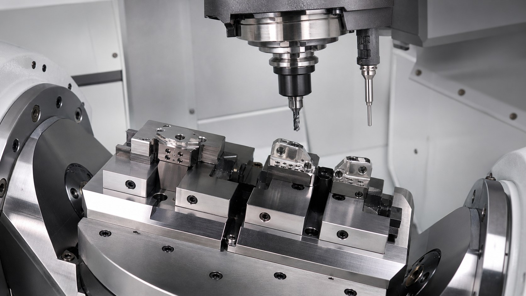
The process plan first creates and verifies the locating faces, then roughs the clamp opening, mounting features and material reliefs. Finish the guide bore and mating seats in a setup that preserves their relationship to those datums. A split clamp can spring when released, so measure the relevant diameter or axis in the functional clamped state as well as documenting its free condition. Thin ears around a locking screw need support during machining without introducing distortion. Tool paths for titanium should manage heat and tool wear, especially at small bores and slots. Record fixture and program revisions with the first-article results.
Threads and locking force
A screw hole is part of the load path, not merely a catalog feature. Confirm thread size, engagement length, counterbore, screw head clearance and whether the screw can be reached when the guide is assembled. The designer should define the required clamping method and any torque limit; a machine shop should not invent a value. Inspect threads with suitable gauges and verify that a mating screw runs without cross-threading. Burrs at the thread exit can prevent the split faces from closing evenly, shifting the guide axis. If locking hardware is supplied separately, trial fit with the intended hardware before approving the first article.
Control edges and surface damage
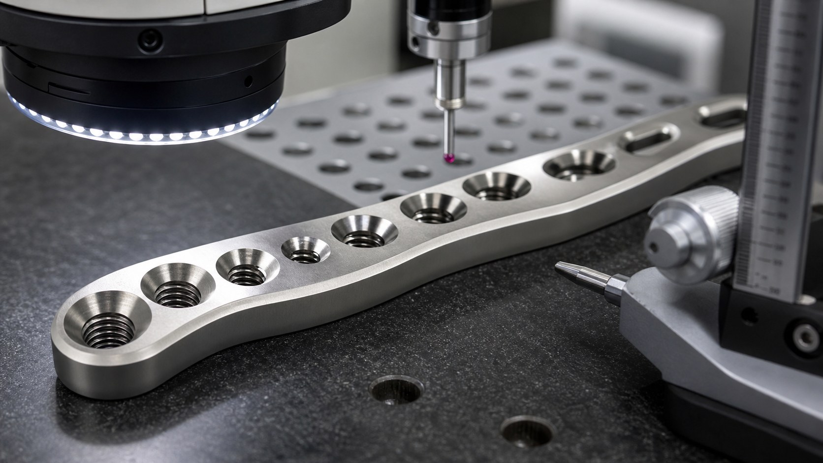
At a bushing bore, a small exit burr can scratch the sleeve or change its seating. At the split slot, an overly aggressive edge break can change clamp compliance. The drawing should distinguish handling edges from functional contact edges and specify where a radius, chamfer or maximum burr is required. Verify both sides of cross-holes and slots with optical inspection when direct viewing is difficult. Finishing and cleaning steps should not hide damage under a cosmetic surface. If an anodized, passivated or coated surface is specified, check dimensions and contact faces after treatment because coating thickness can change fits.
Measure what controls the axis
A first-article report should capture guide-axis position and orientation relative to functional datums, bushing bore size, clamp gap, mounting holes, thread quality and the fit of the representative sleeve. Coordinate measurement can check geometric relationships; bore gauges and optical methods can support smaller features. State the assembly condition during inspection, the gauge used and the measurement uncertainty relevant to the tolerance. A free-state measurement alone may not predict the axis when a clamp is tightened. Maintain a record of nonconformances and approved deviations with the drawing revision and material lot.
Clean, protect and request a useful quote
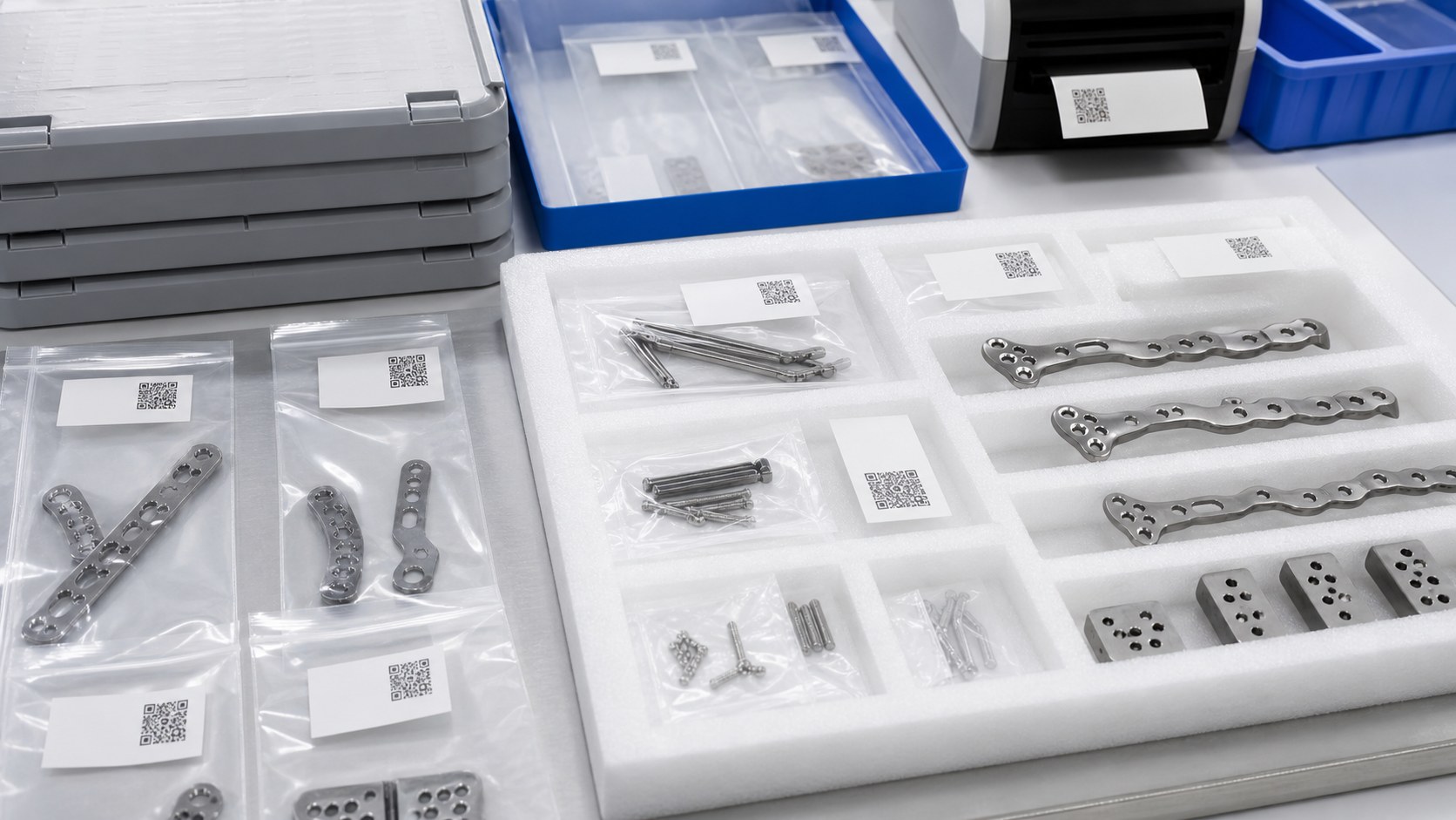
After machining, remove chips from the split and threaded regions and verify no loose particles remain. Protect the bore, contact faces and threads during handling and shipment; a small ding can invalidate an otherwise good first article. Packaging should carry part number, revision and lot identification without unsupported sterile claims. For an RFQ, send the 2D drawing, 3D model, assembly stack, material specification, quantities, critical datums, sleeve and screw data, surface treatment, required inspection method and documentation. That package lets the supplier estimate fixturing, machining, gauges and first-article effort with fewer hidden assumptions.
FAQ
Why is bore diameter alone insufficient?
The guide's function also depends on axis position and angle relative to the mounting datums, bushing fit and clamp state.
Should the clamp be inspected open or tightened?
Both states may be useful, but the device designer should define the functional assembled condition and acceptance method.
Does Ti-6Al-4V make a guide medically approved?
No. Material choice is only one design input; the device manufacturer validates the complete device and its intended use.
What thread details belong on the drawing?
Specify thread size and class, useful depth, counterbore, access, mating hardware and any assembly torque requirement set by the designer.
How are slot and bore burrs checked?
Define edge criteria, remove burrs with a controlled method and inspect both sides optically or with a borescope when needed.
What is needed for an RFQ?
Provide drawings, model, assembly and sleeve data, material, quantities, critical datums, surface finish, inspection and documentation requirements.