
Quadruped and humanoid robot parts may both look like precision robot structures, but their machining priorities are not the same. The key difference is not the outer shape. It is the load path, assembly density, datum chain and inspection focus behind the part.
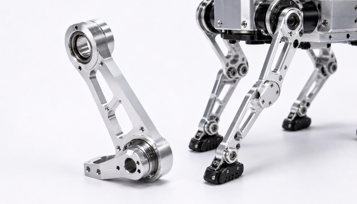
Quadruped robot parts commonly include leg links, hip brackets, knee structures and foot-end connectors. They face repeated impact, ground reaction force and vibration. Humanoid robot parts more often emphasize compact joints, lightweight cavities, sensor mounting faces and multi-axis assembly stability.
For the same aluminum bracket, a quadruped project may focus on impact load, fatigue, pin-bore wear and transition radii. A humanoid project may focus on coaxiality, end-face runout, lightweight pockets and dimensional consistency after surface treatment.
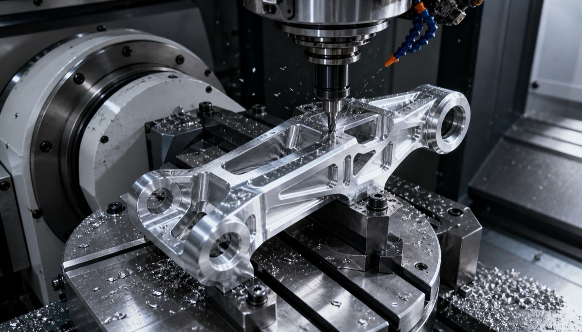
Quadruped and Humanoid Robot Part Machining Comparison
| Comparison item | Quadruped robot focus | Humanoid robot focus | Process reminder |
|---|---|---|---|
| Load behavior | Landing impact, cyclic vibration and leg-force transfer | Joint torque, multi-axis posture and tight space | Confirm main load direction and critical bearing faces early |
| Typical parts | Leg links, foot supports, hip and knee joint parts | Joint housings, lightweight brackets and sensor mounts | Part function should drive the inspection datum |
| Material selection | 7075, titanium and stainless steel are common in high-load zones | 6061, 7075 and engineering plastics may balance light weight | Review material and surface treatment together |
| Tolerance focus | Hole spacing, parallelism, pin-bore wear and end-face contact | Coaxiality, position tolerance, flatness and assembly datums | CMM inspection should cover key holes and faces |
| Delivery risk | Impact-zone burrs, crack initiators and scratched bores | Thin-wall deformation, interference and anodizing size change | Record first-article data and repeat-order process data |
Quadruped Robot Parts Are More Sensitive to Impact and Fatigue
Leg structures in a quadruped robot work under repeated load. Foot contact, step impact, turning and fast acceleration transmit force into links, supports and joint interfaces.
If an inner corner is too sharp, a tool mark sits across the load direction or a pin-hole burr is left uncontrolled, the part may develop a fatigue risk. Machining is therefore not just about milling the shape; it is about protecting the load-bearing holes, contact faces and transition radii.
For 7075 aluminum, titanium or stainless steel parts, material stress, tool wear and local heat should also be considered. Machine accuracy alone cannot solve every impact-related risk.
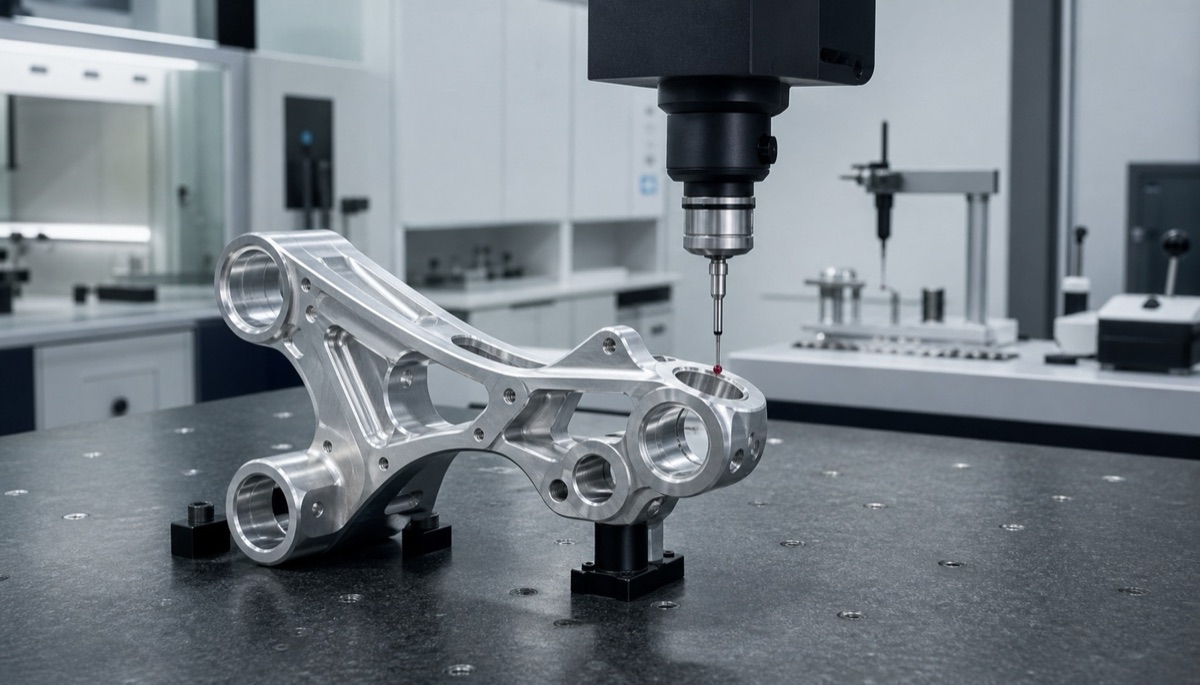
Humanoid Robot Parts Are More Sensitive to Assembly Chain Error
Humanoid robot joints are dense. A single part may support a motor, reducer, encoder, IMU, cable routing and a sensor bracket. A slightly uneven mounting face can affect posture calibration, and a shifted hole pattern can create assembly binding.
For these parts, machining datums should match assembly datums whenever possible. Complex surfaces may justify 5-axis CNC machining if it reduces refixturing. Thin-wall housings often need staged machining, soft jaws or vacuum support to reduce deformation.
The goal is not only a good first article. The process should keep datum relationships stable when the prototype moves into small-batch repeat orders.
What to Confirm Before Quotation
- Whether the part belongs to a quadruped robot or humanoid robot, and its exact installation position.
- Main load direction, motion frequency, impact condition and fatigue expectation.
- Critical bores, locating faces, contact faces and ordinary clearance areas.
- Material grade, heat-treatment state, surface treatment and whether post-finish inspection is needed.
- First-article report, CMM inspection, batch sampling and repeat-order record requirements.
Example: Separating Load Bores from Lightweight Pockets
In one robot leg-connection bracket review, OEMach separated the process for force-bearing pin bores, end-face contact areas and lightweight cavities. The pin bores were left with finish allowance, and hole spacing plus parallelism were checked after semi-finishing.
Lightweight pockets were machined in stages to reduce deformation. Burr direction and edge breaks near the load path were reviewed before final machining, so hand deburring would not change functional geometry.
This zone-based control reduced first-article rework and made the process easier to repeat in later small-batch production.
Common Mistakes
The first mistake is assuming the difference is only visual. In practice, quadruped and humanoid robot parts differ more in force path and assembly logic than in appearance.
The second mistake is quoting every robot part with one tolerance strategy. Impact links, joint housings, sensor brackets and lightweight shells each need a different control focus.
The third mistake is ignoring repeatability. Prototype projects should keep machining and inspection records so the next batch does not restart from zero.
Summary
Quadruped robot parts emphasize impact load, fatigue control, wear resistance and leg-structure strength. Humanoid robot parts emphasize compact joints, posture stability, lightweight structures and multi-axis assembly relationships. A useful CNC machining review should start from the part location, load direction and inspection datum.
FAQ
What is the hardest part of quadruped robot part machining?
Controlling repeated impact, force-bearing bores, transition radii, burrs and fatigue-related risks.
What matters most in humanoid robot part machining?
Lightweight structure, assembly datums, coaxiality, flatness, position tolerance and dimensional consistency after surface treatment.
Can one supplier machine both types of robot parts?
Yes, if the supplier can separate load, material, workholding and inspection requirements instead of using one generic process.
What materials are common for quadruped robot parts?
6061, 7075, titanium alloy and stainless steel are common, depending on weight, strength, wear resistance and cost.
Which robot projects fit OEMach?
OEMach supports small-batch precision machining for robot structures, joint brackets, leg links, sensor mounts and custom components.
Ready to get a quote for your CNC machined parts?
Submit your engineering drawings to qiancj@oemach.com. We support prototype sampling and small-batch production with strict tolerance control.