
7075 thin-wall aluminum parts should not be repaired only after deformation appears. The stable approach is to plan residual stress release, stock-removal sequence, fixture support and post-treatment inspection before machining starts.
7075 aluminum is strong and attractive for lightweight robot arms, optical brackets, aerospace-style mounts and high-strength custom parts. But high stock removal and thin walls can amplify residual stress release, causing flatness drift, hole-position change or local warpage after unclamping.
OEMach reviews material condition, rough-finish separation, balanced cutting, soft fixture support and final-state inspection before accepting tight-tolerance 7075 thin-wall work.
Five Practical Controls for 7075 Thin-Wall Deformation
| Control method | Purpose | Process action | Acceptance check |
|---|---|---|---|
| Confirm material condition | Reduce batch variation and residual-stress risk | Specify 7075-T6, T651 or another condition and keep incoming material records | Retain material certificate and first-article records for critical dimensions |
| Separate roughing and finishing | Release stress before final tolerance features are cut | Rough machine with allowance, then semi-finish and finish after stabilization | Recheck datum faces, flatness and hole relationships |
| Remove stock symmetrically | Reduce warpage caused by one-sided stress release | Balance cutting on thin walls, frames, pockets and light-weighted windows | Inspect wall thickness, outside profile and relative hole positions |
| Use soft fixtures or vacuum support | Avoid deforming thin walls with direct clamping force | Use soft jaws, form-fit fixtures, vacuum plates or auxiliary support | Measure the released free state, not only the clamped state |
| Reinspect after treatment | Control dimensional changes after anodizing, blasting or cleaning | Define masking, coating thickness and critical post-treatment faces early | Recheck key holes, assembly faces and appearance consistency after treatment |
Why 7075 Thin-Wall Parts Lose Stability
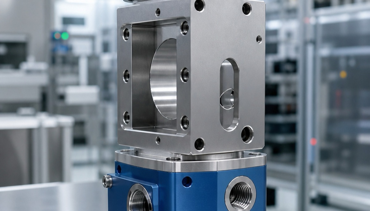
Thin walls have low stiffness. Clamping force, cutting force and machining heat can all create small elastic movement during machining. 7075 has high strength, but a high-removal part can still move when internal stress is released.
The part may look correct while it is clamped. After release, or after anodizing and cleaning, the same part may show flatness failure, changed hole spacing or local bowing. This is why process control must distinguish between the in-process state and the free state delivered to the customer.
Process Parameters Are Not a Fixed Answer
Engineers often ask for one speed and feed value for 7075 thin walls. In practice, parameters depend on cutter diameter, wall thickness, tool overhang, machine rigidity, chip evacuation and coolant strategy.
The more useful goal is stable cutting load. Avoid excessive heat in one local area, keep tool engagement predictable and do not remove too much allowance in the final pass.
For high-accuracy thin-wall parts, the process sheet should state tolerance targets, inspection method and released-state remeasurement requirements before production starts.
Fixture Support Decides the Real Result
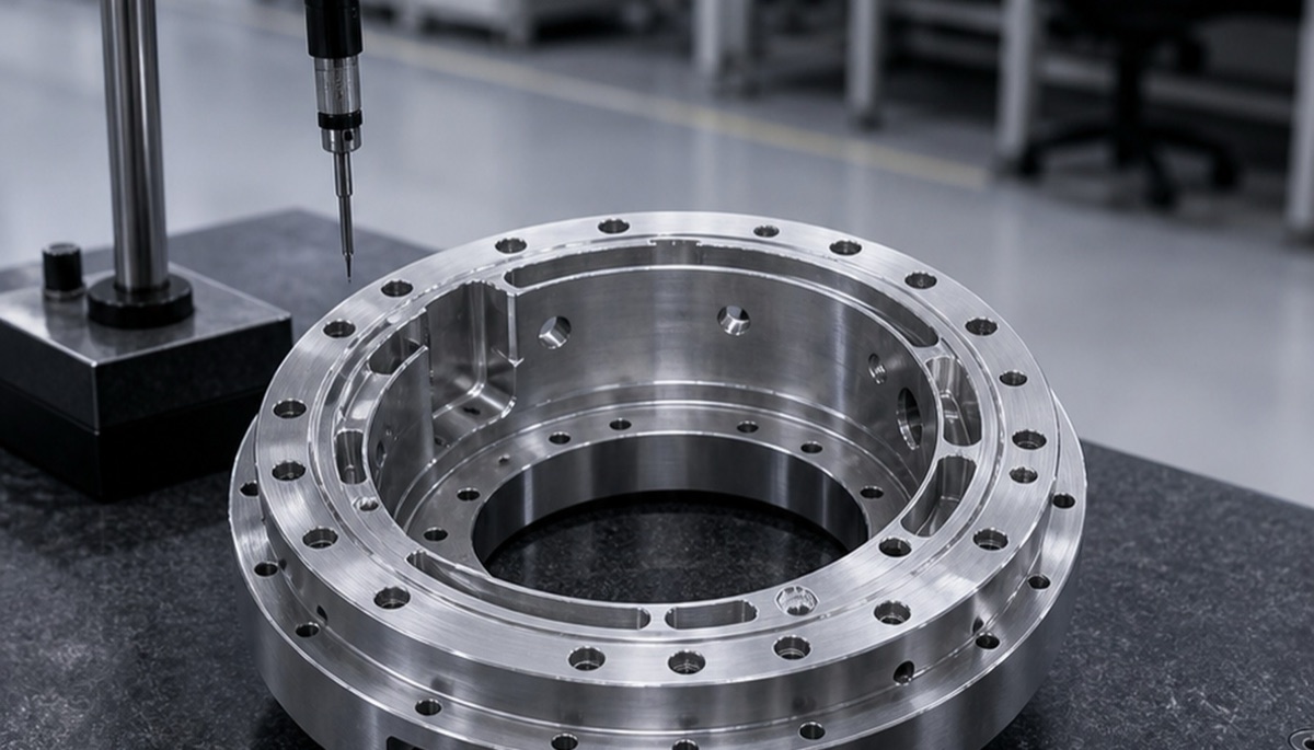
A thin part can be made to measure well if the fixture forces it into shape. That does not mean it will assemble well. Soft jaws, form-fit support, vacuum plates and auxiliary supports should hold the part without bending the functional faces.
For robot lightweight brackets and optical mounts, support should follow stiff areas and avoid pushing directly on weak windows or thin ribs. Release checks after roughing help reveal movement before final tolerance features are cut.
Surface Treatment Must Be Included in the Plan
Anodizing, bead blasting and cleaning can all change the final condition. Film thickness can affect holes and fits, while blasting and handling may expose burrs or appearance inconsistency.
Critical holes, assembly faces and masking areas should be marked before machining. The accepted dimension should be defined in the final treated state when those features are functionally important.
RFQ Advice for Engineers and Buyers
- Provide the minimum wall thickness, critical assembly faces and allowed flatness.
- Specify 7075 condition, coating thickness, masking areas and appearance requirements.
- Identify inspection datums and whether free-state measurement is required.
- Ask whether roughing and finishing will be separated and whether support fixtures are needed.
- Request first-article records for key dimensions after post-treatment when fit is critical.
Common Mistakes
The first mistake is assuming thin-wall deformation can always be corrected later. Straightening may introduce new stress and is not suitable for many precision parts.
The second is measuring only while the part is clamped. Thin-wall parts must be evaluated in the released condition. The third is ignoring surface treatment, even though anodizing, blasting and cleaning can change the final assembly state.
Summary
7075 thin-wall deformation control is a process problem, not a final-inspection problem. Material condition, rough-finish separation, balanced stock removal, low-distortion fixturing and post-treatment inspection should be planned together from the start.
FAQ
Why do 7075 thin-wall parts deform?
Residual stress, uneven stock removal, clamping force, cutting heat and surface treatment can all move a low-stiffness thin-wall structure.
Are vacuum fixtures suitable for 7075 thin-wall parts?
They can be suitable for some flat or plate-like parts, but sealing area, cutting force and auxiliary locating support must be reviewed first.
Is rough-finish separation always necessary?
For high-removal or high-accuracy thin-wall parts, rough-finish separation is usually recommended so stress can release before critical finishing.
Why inspect after surface treatment?
Coating thickness, blasting and handling can affect holes, assembly faces and appearance consistency. The final acceptance state should match the treated condition.
Can OEMach support small-batch 7075 thin-wall machining?
Yes. OEMach can design CNC process routes and inspection plans based on wall thickness, assembly datums and surface-treatment requirements.
Ready to get a quote for your CNC machined parts?
Submit your engineering drawings to qiancj@oemach.com. We support prototype sampling and small-batch production with strict tolerance control.