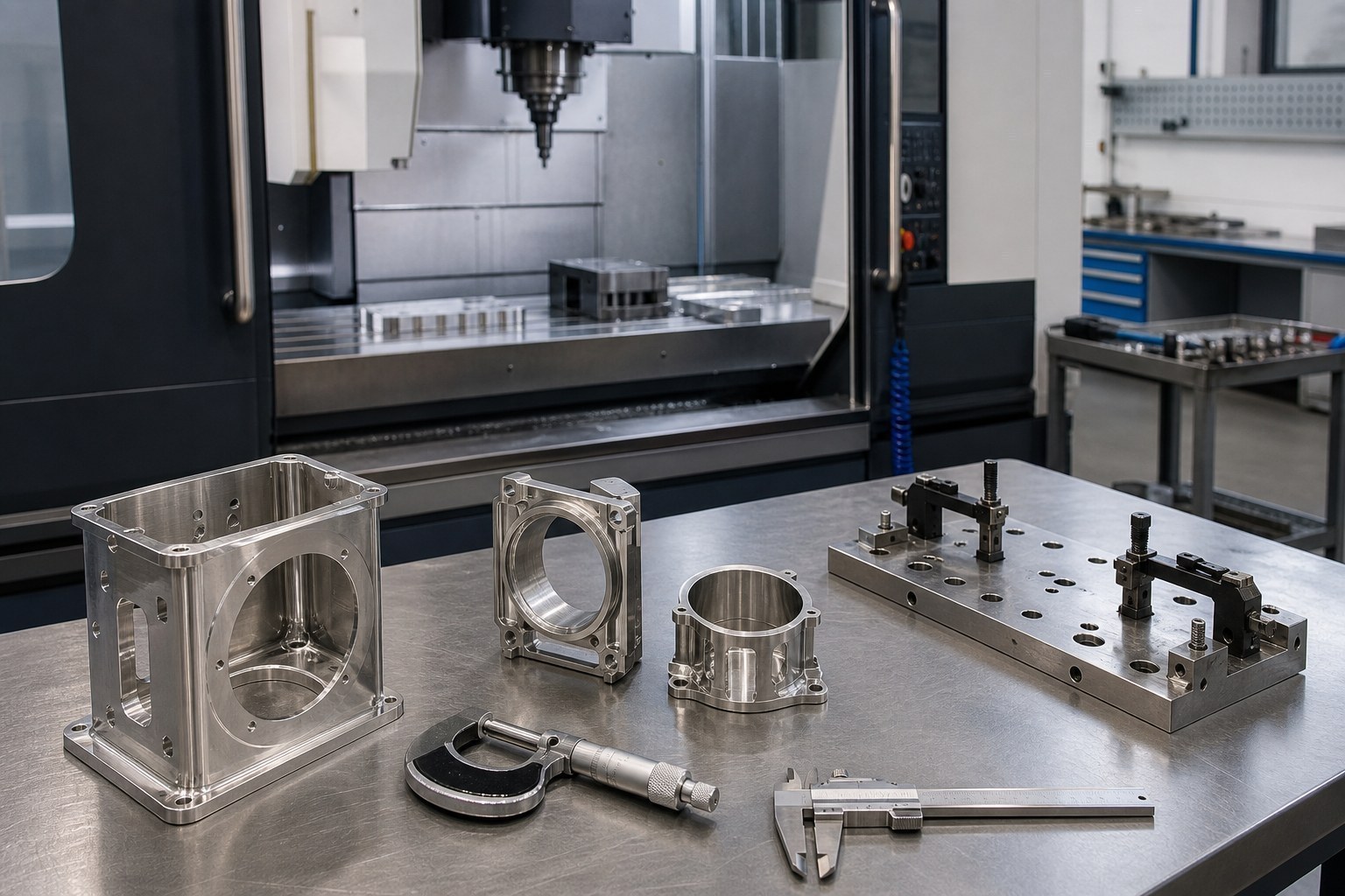
Summary
Thin-walled stainless steel parts can move under clamping force, cutting heat, tool pressure, and residual stress. For low-volume custom machining projects, OEMACHfirst reviews functional surfaces, datum relationships, and deformation-sensitive areas before defining staged machining and dimensional verification. Fixed cutting values are intentionally omitted because they must be established from the actual material condition, geometry, machine, and tooling.
Background and application scenario
Thin-walled stainless steel components are common in automation equipment, precision assemblies, covers, brackets, housings, and fluid-handling structures. Their low local rigidity means that a part may appear stable while clamped but recover after removal. Open edges, deep pockets, narrow ribs, and uneven stock distribution can amplify this behavior.
Individually specified tolerances must be read directly from the drawing. Dimensions without individual tolerance indications must be interpreted according to the general tolerance system identified in the technical documentation.[Source: ISO 2768-1:1989]
Key machining risks
• Excessive clamping can elastically distort a wall or open edge.
• Uneven stock removal can release internal stress asymmetrically.
• Concentrated cutting heat can create temporary movement during machining.
• Repeated datum changes can accumulate dimensional error.
• Surface-finish operations can still deform a weak section if cutting load is not controlled.
Geometrical requirements such as flatness, perpendicularity, position, and profile must be linked to the specified datum framework.[Source: ISO 1101:2017] Surface texture requirements should be interpreted from the technical specification instead of being assumed from appearance alone.[Source: ISO 21920-1:2021]
Process recommendations
Begin by separating functional surfaces from non-critical external geometry. Establish a stable datum, use broad and repeatable support, and keep clamping loads away from weak edges where practical. Remove material in stages, recheck the released condition, and reserve finishing decisions until the dimensional trend is understood.
Tool paths should avoid prolonged heat concentration in one flexible region. Tool condition, chip evacuation, coolant delivery, and actual machine behavior should be reviewed during first-piece machining. No universal stock allowance or cutting parameter is suitable for every thin-wall geometry.
Critical dimensions should be verified after unclamping under an agreed support and temperature condition. Hole-and-shaft fits must be interpreted through the specified basic size, tolerance zone, and fit relationship.[Source: ISO 286-1:2010]
Service process and commitment
A practical workflow covers drawing review, clarification of missing requirements, fixture planning, first-piece machining, released-condition verification, customer confirmation, and controlled continuation of the batch. OEMACH can follow the mutually confirmed drawing and retain ordinary first-piece and process records. It does not promise zero deformation when material condition, datum definition, or functional requirements remain unspecified.
FAQ
Can a thin-walled part be completed in one setup?
It depends on access, datum relationships, and stock distribution. One setup may reduce datum-transfer error, while staged machining may better manage stress release.
Does higher clamping force improve accuracy?
Not necessarily. Excessive force can distort the part while it is held and cause springback after release.
Why can dimensions change after removal from the fixture?
Clamping recovery, temperature change, altered support, and stress redistribution are common contributors.
Is first-piece confirmation useful for a small batch?
Yes. It helps evaluate fixturing, tool paths, dimensional trends, deburring, and released-condition behavior before continuing.
What information should accompany an RFQ?
Provide material and condition, functional dimensions, tolerances, datums, surface texture, finishing requirements, assembly purpose, quantity, and delivery expectations.
Scan to contact us
Contact: Allen
Email: shiziqiu@oemach.com
My whatsapp code