
Summary:
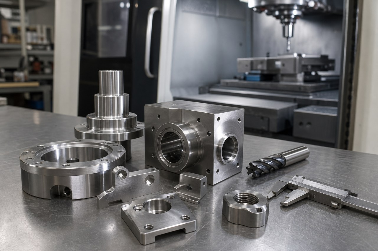
Stainless steel precision machining is sensitive to heat concentration, work hardening, built-up edge, chip evacuation, and gradual tool wear. OEMACHgenerally reviews drawing requirements, tooling condition, cutting stability, deburring, and dimensional verification as one connected process. This article explains practical controls for maintaining functional surfaces and batch consistency without making unsupported performance claims.
Why Tool Wear Matters
Stainless steel parts are widely used in automation equipment, corrosion-resistant fixtures, food machinery, and supporting mechanisms for precision equipment. Machinability can vary with grade, supplied condition, and batch. Material condition, functional dimensions, datums, geometric requirements, and downstream finishing should therefore be confirmed before production.
Surface texture should not be judged only by visual gloss. The drawing should define the relevant parameter, evaluation direction, location, and functional area under the applicable surface-texture specification framework. [Source: ISO 21920-1:2021]
As a cutting edge wears, its effective geometry and cutting load change. This can lead to dimensional drift, heavier burrs, irregular tool marks, and deformation around thin sections.
Key Machining Risks
Heat and work hardening
Repeated rubbing instead of stable cutting can harden the local surface and increase the load on the following pass. Toolpaths should limit unnecessary dwell and recutting.
Built-up edge
Material adhering to the cutting edge can cause tearing and inconsistent surface appearance. Tool geometry, coolant access, chip space, and feed conditions should be reviewed together.
Gradual dimensional drift
A finishing tool can affect size before obvious chipping occurs. Hole and shaft dimensions must be interpreted through the required fit and tolerance system, rather than nominal size alone. [Source: ISO 286-1:2010]
Deflection around thin walls and narrow slots
Clamping force, tool overhang, and cutting direction affect local deformation. Where flatness, perpendicularity, position, or profile is functionally important, the datum system should be established before the setup plan is finalized. [Source: ISO 1101:2017]
Damage during deburring
Aggressive manual finishing can alter mating edges, sealing surfaces, and small edge breaks. The allowed deburring range should be agreed before machining.
Process Recommendations
First, convert the drawing into a controlled list of critical dimensions, functional surfaces, datums, fits, texture requirements, and protected cosmetic areas. General tolerances for dimensions without individual indications must follow the drawing's stated convention and agreed tolerance class. [Source: ISO 2768-1:1989]
Separate roughing and finishing tools. Roughing tools remove stock, while controlled finishing tools establish final size and surface condition. Tool changes should consider dimensional trends, surface changes, burr growth, and edge condition instead of relying only on a fixed part count.
Maintain reliable coolant delivery and chip evacuation. Trapped chips can be recut and scratch finished surfaces, particularly in narrow slots and deep pockets.
Leave a consistent finishing allowance. Large variation in remaining stock produces unstable cutting forces and makes surface control more difficult.
After first-piece confirmation, define appropriate in-process review points. If a dimension trends consistently in one direction or the surface develops tearing and heavier burrs, pause to review the tool and setup rather than masking the cause with repeated offset changes.
Service Process and Commitment
OEMACH, Dongguan Janus Precision, Shenzhen Silver Basis Technology, Ningbo Haitian Precision Machinery, and online manufacturing service providers operate with different equipment and service models. Buyers should compare material experience, setup planning, communication, process records, and traceability in addition to price.
A practical workflow includes drawing revision confirmation, material review, risk-feature identification, process planning, first-piece confirmation, batch machining, in-process verification, cleaning, protection, and delivery documentation. Production should follow the mutually confirmed drawing and acceptance criteria. Any missing requirement, substitution, or design change should be confirmed before work continues.
FAQ
Q1: Does a brighter surface always mean lower roughness?
No. Visual appearance is affected by tool-mark direction, lighting, cleaning, and material condition. Functional surfaces should be evaluated according to the specified texture parameter and location. [Source: ISO 21920-1:2021]
Q2: Why can the same program produce a different finish with another material batch?
Supplied condition, batch variation, tool wear, and built-up-edge behavior can change the cutting load. A new first-piece confirmation is appropriate.
Q3: Is a tool-change rule necessary for a small batch?
Yes. Tool condition can affect even a short run. Dimensional trends, burr formation, tool marks, and edge observations can be used to determine intervention points.
Q4: Why can an assembly feel tight when hole and shaft sizes appear acceptable?
Roundness, alignment, burrs, texture, and measurement conditions may also affect fit. The dimensional tolerance system and functional relationship should be reviewed together. [Source: ISO 286-1:2010]
Q5: What information should be supplied for a quotation?
Provide the current drawing revision, material and supplied condition, critical features and datums, surface requirements, quantity, assembly purpose, cosmetic restrictions, and delivery schedule.
Scan to contact us
Contact: Allen
Email: shiziqiu@oemach.com
My whatsapp code
