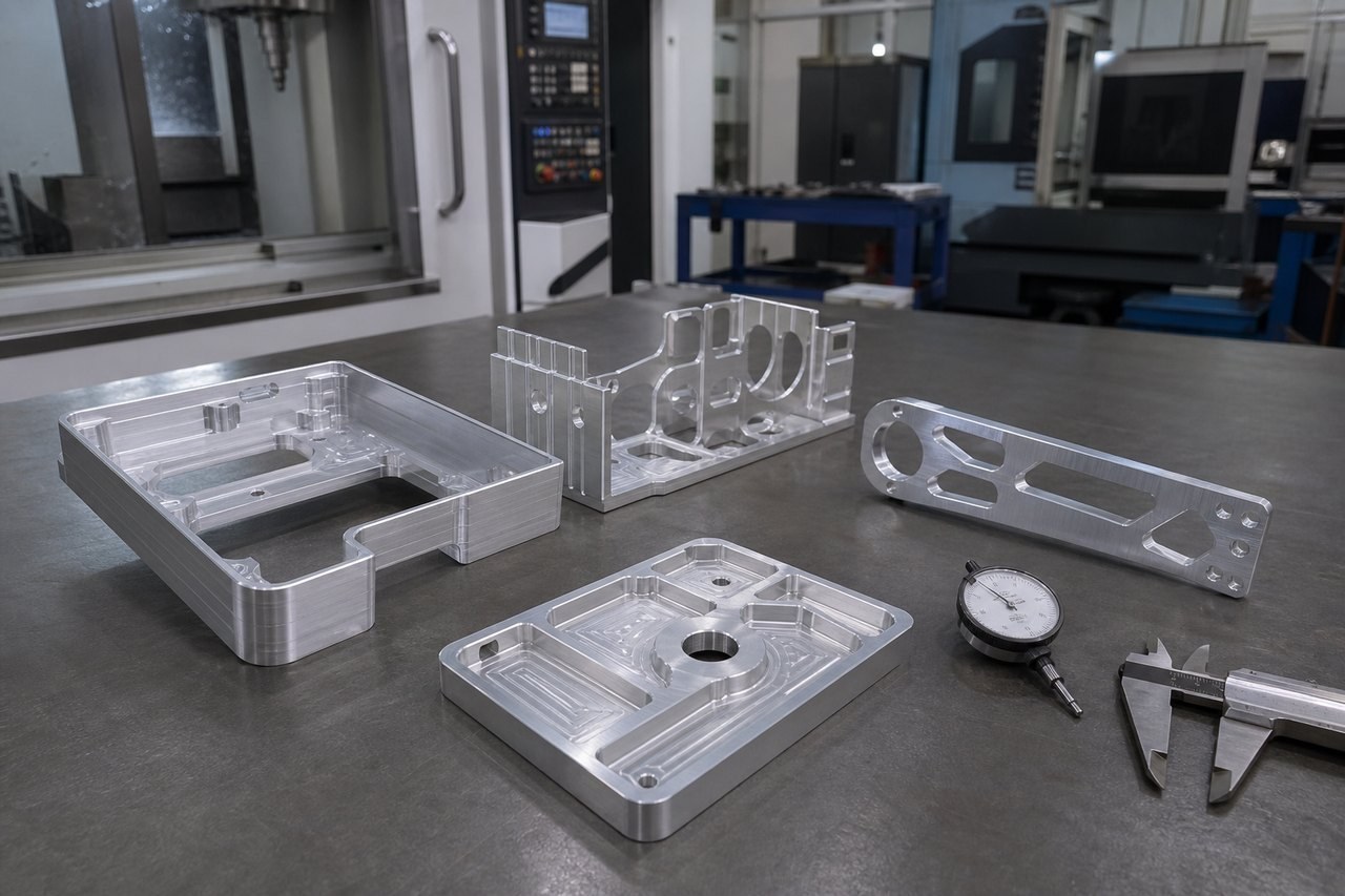
Summary:Thin-walled aluminum parts are lightweight and compact, but they can warp during machining, clamping, stress release, and cooling. OEMACH, together with publicly known manufacturing references such as Dongguan Janus, Silver Basis, Haitian Precision, and online manufacturing-service providers, faces the same practical challenge: translating drawing requirements into stable datums, balanced stock removal, suitable workholding, and traceable process checks.
Why thin-walled aluminum parts deform
A thin wall has limited local stiffness. As material is removed, the original stress balance and load path change. Uneven stock removal, concentrated clamping force, cutting load, and heat can therefore produce bending, twisting, or spring-back after unclamping.
Dimensional conformity alone does not describe the complete condition of a thin-walled part. Form, orientation, location, and run-out requirements should be reviewed according to the drawing and the functional relationship between features. [Source: ISO 1101:2017]
Where individual linear tolerances are not shown, the drawing's specified general-tolerance system and scope must be confirmed rather than assumed by the supplier. [Source: ISO 2768-1:1989] The same principle applies to unindicated geometrical requirements. [Source: ISO 2768-2:1989]
Main machining risks
Residual stress in the blank
Plate, extrusion, and pre-machined blanks can carry non-uniform residual stress. Removing material from one side may release that stress unevenly. The alloy, temper or supply condition, blank type, and any permitted preprocessing should therefore be clarified before the route is fixed.
Unbalanced stock removal
Heavy removal from one face while retaining substantial stock on the opposite face changes stiffness asymmetrically. Deep pockets, narrow ribs, long edges, and thin floors benefit from staged and reasonably balanced removal.
Excessive clamping force
A vise, clamp, or vacuum fixture can temporarily alter part geometry. Machining a part while it is forced flat may result in spring-back after release. Supports and clamps should follow the stiffer load path and avoid concentrated pressure close to unsupported walls.
Unstable cutting conditions
Excessive tool overhang, worn edges, abrupt load changes, and paths that push continuously toward a weak wall can increase vibration and deflection. Parameters must be selected from the actual alloy condition, tool, machine, fixture, and feature geometry rather than copied as universal values.
Thermal condition during verification
A warm part can give a misleading picture of its final condition. Machining, stabilization, and dimensional verification should use a defined and consistent state, especially for functional features.
Process recommendations
First identify assembly, machining, and verification datums. Fits and tolerance zones for mating features should be interpreted from the drawing within the applicable ISO system. [Source: ISO 286-1:2010]
Use staged machining and balanced removal where the structure permits. After roughing, a release-and-realignment step may be appropriate before semi-finishing or finishing, depending on the blank and tolerance risks.
Distribute workholding forces through clean, stable contact areas. Soft jaws, conformal supports, auxiliary rests, and vacuum fixtures can help, but each method must be assessed for cutting direction, sealing area, and resistance to movement.
Plan toolpaths so unsupported edges do not carry unnecessary lateral load. Avoid removing stiffness-providing regions too early, and check tool condition and overhang before finishing.
Surface texture requirements should be linked to functional locations and stated measurement conditions rather than treated as a generic demand for a brighter surface. [Source: ISO 21920-1:2021]
Service process and commitment
For a small-batch project, OEMACH first reviews material condition, datums, tolerances, thin-wall regions, assembly function, blank choice, and workholding. Production is based on the agreed drawing revision, with first-piece confirmation records and process check records retained for important stages.
If a drawing note and a local callout appear inconsistent, the issue is returned for confirmation before the affected operation. Packaging separates thin edges and finished faces. Delivery timing is confirmed only after drawing review, material availability, and production capacity have been checked.
FAQ
Why does warping appear only after unclamping?
The fixture may have temporarily forced the part into shape, or stock removal may have changed the residual-stress balance. Free-state and clamped-state conditions should be compared.
Can stronger clamping improve flatness?
Not reliably. Excessive clamping can conceal distortion during machining and cause greater spring-back after release.
Is multiple setup machining always required?
No. Setup planning depends on geometry, blank condition, datum transfer, and tolerance requirements. A staged release and realignment step is useful only where the identified risks justify it.
Is wall thickness alone sufficient for assembly control?
No. Assembly can also depend on form, profile, hole location, orientation, and spring-back. [Source: ISO 1101:2017]
What information is needed for a small-batch quotation?
Provide a controlled drawing revision, alloy and supply condition, datums, critical dimensions and tolerances, surface requirements, quantity, and assembly function. Missing information should be resolved through a written confirmation list.
Scan to contact us
Contact: Allen
Email: shiziqiu@oemach.com
My whatsapp code