
For humanoid robot foot load-bearing parts, impact comes before weight reduction. Foot pads, ankle connection blocks, buffer mounts and force-sensor datum parts repeatedly see landing shocks, side torque and alternating loads during gait adjustment.
If the wall thickness and ribs are pushed too far for lightweight design, a prototype may pass static assembly but fail in dynamic testing through stripped threads, dented locating faces, sensor zero drift or local fatigue cracks.
OEMach evaluates strength, toughness, heat-treatment state, clamping deformation and CMM inspection together. For key datums in the ±0.005 mm to ±0.02 mm range, the question is not only whether the dimension can be made, but whether it remains stable after impact and repeated loading.
Material Selection Under Impact Loads
| Material | Typical location | Advantage | Watch point |
|---|---|---|---|
| 7075 aluminum | Foot brackets and lightweight connection blocks | High strength, low weight and efficient CNC machining | Control sharp-corner stress, anodizing effects and clamping deformation |
| TC4 titanium | High-strength thin-wall links and local impact parts | High specific strength and good fatigue potential | Slow machining, high tool wear and higher quoting risk |
| 17-4PH / stainless steel | Pin seats, wear zones and thread load areas | Good strength and wear resistance | Higher weight; local use is usually more reasonable |
| PEEK / nylon | Buffer pads, insulating pads and light-duty bushings | Damping, insulation and low weight | Load and temperature limits must be defined clearly |
| Hybrid design | Metal skeleton with buffer elements | Balances stiffness, strength and damping | Assembly datum, preload and interface tolerance must be defined early |
Why Impact Load Changes the Machining Decision
A part that survives static loading may still be unstable under repeated landing impact. Foot components can see short peak loads at touchdown, so material strength must be considered together with fatigue behavior, radius transitions, chamfers and rib design.
Machining review should pay special attention to sharp internal corners, thin walls, thread roots and sensor mounting faces. Sharp corners create stress concentration. Thin walls amplify clamping deformation. If threaded holes are not stable, impact can loosen or damage them during testing.
For force-sensor mounting parts, flatness and hole position matter as much as raw strength. Once the datum deforms, sensor readings may drift even when the visible part looks acceptable.
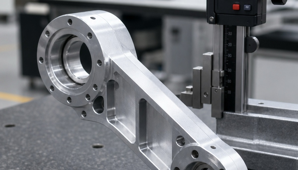
Machining Plan: Define Material, Clamping and Inspection Together
Aluminum foot components are often best planned with 5-axis or 4-axis multi-face machining to reduce repeated flipping. Critical datums should be finished late, after roughing has released most internal stress.
For 7075 aluminum, avoid deep-cavity heavy cuts that release stress unevenly. Roughing and finishing should be separated when the part includes large pockets, slender ribs or bearing-related datums.
TC4 titanium is worth evaluating for high-strength thin-wall or local load-bearing parts, but cutting speed is low and heat is concentrated. Tooling, coolant and inspection plans need to be confirmed before the RFQ is treated as a normal aluminum job.
Stainless steel is often better used locally for wear, threads or pin-seat areas instead of making the whole part heavy. For mixed-material foot structures, the interface tolerance and preload must be part of the drawing review.
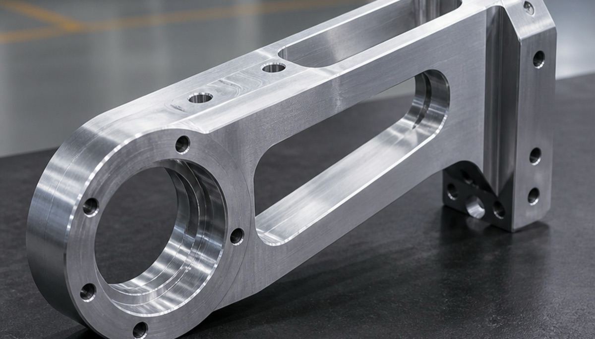
Engineering Example: Start From the Load Path
In one humanoid robot foot-connection project, the customer initially focused on outside dimensions and weight-reduction pockets and wanted a quick 7075 aluminum prototype. During drawing review, OEMach found that the sensor mounting face, ankle connection hole and foot support ribs sat on the same impact path.
The process was adjusted to rough machining for stress release, late finishing of key datum faces and CMM reporting around holes, flatness and end-face perpendicularity. Sharp internal corners were also reviewed for radius improvement, and a steel insert option was discussed for localized threaded load.
The result was a more stable prototype route for later small-batch production. The lesson is simple: for foot load-bearing parts, material and process should be selected backward from the impact path.
Five Questions Before Sending an RFQ
- Is the part carrying static load, impact load or repeated alternating load?
- Which force-bearing faces, sensor datums and ankle connection holes require measured reports?
- Is the material target 7075 aluminum, TC4 titanium, stainless steel or a hybrid metal and PEEK/nylon solution?
- After surface treatment, do holes, threads and locating faces need reinspection?
- Will prototype test feedback on deformation, wear and assembly be written back into the next drawing revision?
Common Mistakes
The first mistake is choosing only by tensile strength and ignoring impact toughness and fatigue life. The second is making ribs and corner radii too aggressive for weight reduction, creating local stress concentration.
The third is checking only hole spacing on sensor mounting parts while ignoring flatness and datum stability after loading. For development teams, a supplier that can discuss material, DFM review, 5-axis machining and inspection feedback is often more useful than one that only quotes a drawing.
Summary
Humanoid robot foot load-bearing part machining is not only about strength. Impact toughness, fatigue life, lightweight structure and assembly datums must be controlled together. 7075 aluminum, TC4 titanium, stainless steel and PEEK or damping parts should be selected by function, not by material grade alone.
FAQ
What materials are used for humanoid robot foot load-bearing parts?
Common choices include 7075 aluminum, TC4 titanium, stainless steel, PEEK and nylon. The right choice depends on load, weight and interface requirements.
Why should foot parts be checked for impact load?
Landing creates short peak loads that can expose risks around sharp corners, threads, thin walls and sensor datum faces.
Is 7075 aluminum suitable for robot foot parts?
Yes, it is suitable for many lightweight brackets and connection blocks, but sharp-corner stress, anodizing effects and clamping deformation must be controlled.
When is TC4 titanium worth using?
TC4 can be evaluated for higher specific strength, fatigue performance or thinner structures, but machining time and cost are higher.
Can OEMach support small-batch robot foot components?
Yes. OEMach supports material review, CNC machining, 5-axis machining, CMM inspection and small-batch custom part production.
Ready to get a quote for your CNC machined parts?
Submit your engineering drawings to qiancj@oemach.com. We support prototype sampling and small-batch production with strict tolerance control.