
Rigid splines and flexsplines are not ordinary gear rings. In harmonic drive mating parts, the rigid spline focuses on internal tooth form, roundness, concentricity, face runout and mounting-hole datum. The flexspline also adds thin-wall thickness, elastic deformation, heat-treatment movement and clamping stress control.
If only the teeth are machined but the gear-ring datum, end-face posture and post-heat-treatment inspection are not controlled, assembly can show meshing noise, backlash variation, local wear or shorter service life. In prototype and small-batch development, these problems are difficult to recover by assembly adjustment alone.
OEMach first reviews the functional relationship among rigid spline, flexspline, bearing seats, connection holes and output faces. Then the process plan connects CNC roughing, wire EDM, grinding, heat treatment and CMM inspection instead of treating each operation separately.
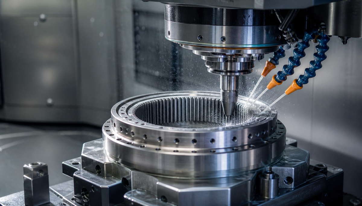
Accuracy Focus for Rigid Splines and Flexsplines
| Part or feature | Key accuracy | Common risk | Process suggestion |
|---|---|---|---|
| Rigid spline | Internal tooth form, roundness, concentricity and face runout | Uneven meshing, higher noise and eccentric assembly | Reinspect after tooth machining and tie mounting datum to gear-ring datum |
| Flexspline | Tooth form, wall-thickness consistency, roundness and elastic-zone deformation | Local stress concentration and reduced service life | Use low-stress clamping and separate roughing from finishing |
| Mounting hole group | Position, pitch and counterbore depth | Reducer assembly skew | Inspect hole group and end-face datum in the same coordinate system |
| After heat treatment | Hardness, deformation and circular runout | Good before heat treatment, out of tolerance afterward | Reserve finishing allowance and regrind or recheck after heat treatment |
| Surface condition | Tooth-surface roughness, burrs and chamfers | Meshing wear and abnormal noise | Deburr tooth roots and hole mouths without damaging tooth form |
Why Rigid Splines Cannot Be Judged Only by Tooth Count and Hole Position
A rigid spline usually carries the fixed gear ring and assembly locating function. Internal tooth accuracy directly affects meshing uniformity, but the mounting end face, outside locating diameter and connection-hole position are just as important.
A tooth profile can pass inspection while face runout remains too large. In that situation, the wave generator and flexspline may still work in an unstable posture. The practical risk is not one failed dimension, but an inconsistent axis relationship after assembly.
A more stable approach is to release stress after roughing, keep finishing allowance after heat treatment, and inspect the gear-ring datum, end face and hole group together. For higher-accuracy projects, roundness, concentricity and face runout should appear in the inspection report, not only on the drawing.
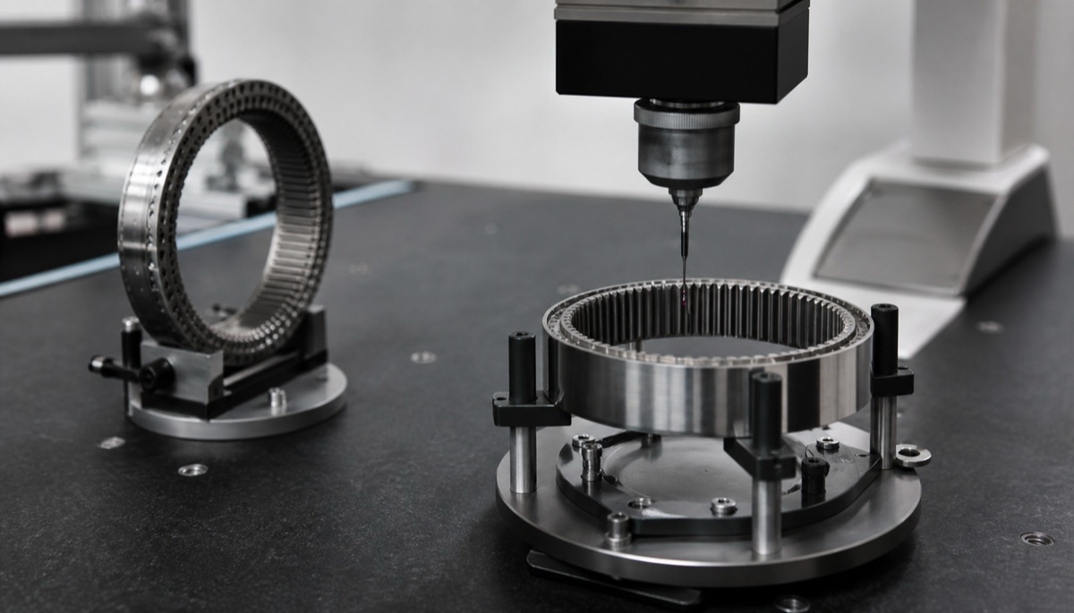
Flexspline Difficulty: Thin Wall and Springback
The flexspline is usually more sensitive to clamping deformation than the rigid spline. A thin wall may look stable inside the fixture and then spring back after unloading. Heat treatment or surface treatment can add new roundness and wall-thickness variation.
Flexspline machining needs controlled clamping force, stock distribution and machining sequence. Heavy one-pass cutting on thin areas should be avoided. Key tooth and end-face features are safer when finished after the part has reached a more stable stress condition.
When buyers request a quote, outside size and material alone are not enough. Tooth inspection, heat-treatment state and wall-thickness requirements must be clear, otherwise the price may look low while the machining risk is high.
Post-Heat-Treatment Reinspection Matters More Than Early Optimism
In one harmonic-drive rigid-spline project, the initial focus was tooth machining and hole position. During drawing review, OEMach identified post-heat-treatment face runout and internal gear-ring concentricity as the main small-batch assembly risks.
The final process used rough machining with reserved allowance, end-face regrinding after heat treatment, key-hole machining after the thermal step, and CMM records for mounting-hole position, face runout and related gear-ring datums. The tooth area also received burr and visual review to avoid local burrs affecting meshing.
This closed loop across pre-heat, post-heat and inspection reduced the chance of assembly noise and rework. For precision transmission parts, the value is not a single machining operation but the connection between process and verification.
Five Questions to Confirm Before Ordering
- Which end face, outside diameter or hole group defines the final assembly datum for the rigid spline and flexspline?
- Is post-heat-treatment regrinding, wire-EDM finishing or secondary inspection required for key features?
- How will tooth form, roundness, concentricity and face runout be measured?
- Can the supplier adjust fixturing strategy and process allowance for thin-wall flexsplines?
- Will the first-article report keep measured values for repeat orders and process reuse?
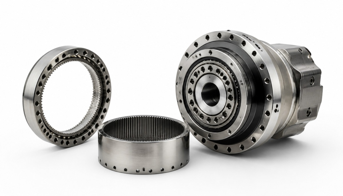
Common Mistakes
The first mistake is checking tooth form while ignoring the concentric relationship between the gear ring and mounting datum. The second is releasing parts because pre-heat-treatment measurements pass, without checking post-heat movement.
The third mistake is treating the flexspline as a normal thin-wall ring. Its elastic working behavior means machining and inspection both need stricter process thinking.
Summary
For harmonic drive rigid spline and flexspline machining, the goal is not simply to produce the teeth. Tooth form, wall thickness, roundness, concentricity and post-heat-treatment stability must pass as one system. Before ordering, engineering teams should define datums, inspection items and post-heat reinspection requirements clearly.
FAQ
What should rigid spline machining control?
It should control internal tooth form, roundness, concentricity, face runout, mounting-hole position and post-heat-treatment stability.
Why is flexspline machining more difficult?
Flexsplines are usually thinner and more sensitive to clamping deformation and springback, while tooth accuracy, wall thickness and elastic-zone stability must also be controlled.
Do harmonic drive mating parts need inspection after heat treatment?
Yes. Heat treatment can change roundness, face runout and hole relationships, so critical parts should keep measured post-heat data.
Can rigid splines and flexsplines be made only by CNC machining?
Some structures can be completed by CNC, but high-accuracy tooth forms, narrow slots or post-heat finishing often need wire EDM, grinding or dedicated tooth-form processes.
Can OEMach support small-batch harmonic drive mating parts?
Yes. OEMach can support small-batch rigid splines, flexsplines, connection rings, mounting seats and related precision mechanical parts with inspection records.
Ready to get a quote for your CNC machined parts?
Submit your engineering drawings to qiancj@oemach.com. We support prototype sampling and small-batch production with strict tolerance control.