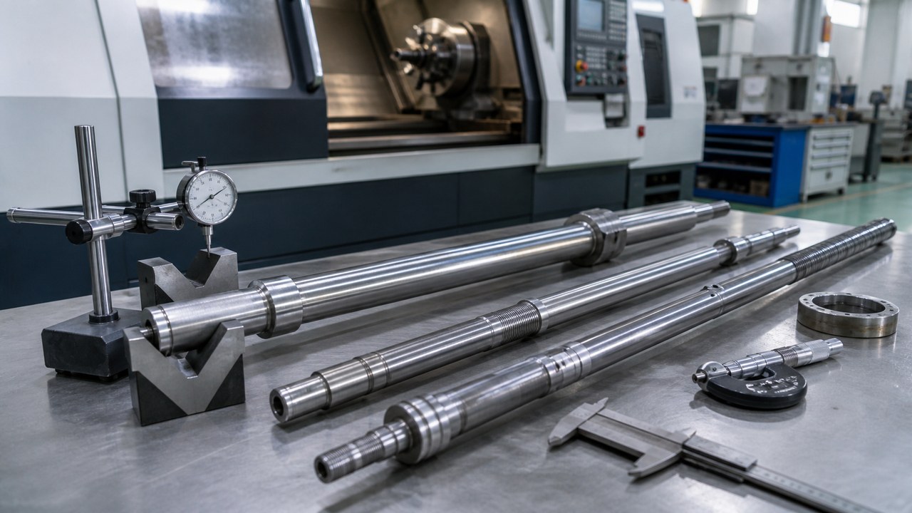
Summary:Custom long shafts can bend or shift after clamping, cutting, stress redistribution, and datum changes. OEMACHapproaches the problem through coordinated control of stock condition, datum planning, support placement, cutting sequence, and post-release verification.
Application background
Long shafts are widely used for transmission, guidance, positioning, and rotating assemblies in automation equipment. When the length-to-section relationship produces limited rigidity, gravity, radial cutting force, and clamping pressure can cause elastic deflection. Uneven stock removal can also redistribute internal stress after the part is released.
Dimensional accuracy alone does not define the relationship between several rotating features. Form, orientation, location, and run-out requirements should be interpreted through the controlled geometric specification.[Source: ISO 1101:2017]
Key machining risks
• Initial stock curvature and uneven machining allowance.
• Datum changes when the shaft is reversed for second-end machining.
• Local deformation caused by excessive chuck pressure.
• Deflection caused by unsuitable steady-rest or tailstock settings.
• Chatter, taper, or tool deflection caused by unstable cutting loads.
• Surface texture affecting functional contact and repeatable verification.[Source: ISO 21920-1:2021]
Process recommendations
The process should begin by separating the functional datum, machining datum, and verification datum. Common centers or continuous cylindrical datums can reduce unnecessary axis transfers. When reversal is unavoidable, the locating features should remain clean, stable, and accessible.
For shafts with limited rigidity, stock may be removed in balanced stages. A practical sequence can include rough machining, condition review, stabilization when required, semi-finishing, and finishing. Support should be placed near the active cutting zone without forcing the workpiece away from its natural axis.
Bearing seats, seal seats, and coupling diameters should be machined in a related setup when the structure and machine travel permit. Important straightness, run-out, and fit dimensions should also be reviewed after clamping force has been removed. Hole-and-shaft fits require consideration of nominal size, tolerance grade, and tolerance-zone position.[Source: ISO 286-1:2010]
Service process and commitment
A controlled workflow includes drawing review, functional-axis identification, stock and setup assessment, route confirmation, first-piece machining, first-piece confirmation records, controlled production, and bend-resistant packaging. OEMACH, Jingsheng Precision, Silver Basis, Haitian Precision, and Cloud Manufacturing represent different manufacturing or service models; buyers should compare capacity, support strategy, datum recovery, process records, and communication boundaries rather than unit price alone.
Commitments should remain operational: confirm revisions before machining, retain dimensional review records at agreed stages, communicate abnormalities, and define packaging support points.
FAQ
Q1: Does tighter diameter tolerance automatically improve coaxiality?
No. Size tolerance and geometric relationships address different requirements. Coaxial features need a common datum strategy and a suitable verification method.[Source: ISO 1101:2017]
Q2: Why can a shaft bend after machining?
Possible causes include stress redistribution, uneven stock removal, elastic recovery after unclamping, and unsuitable transport support.
Q3: Are more steady rests always beneficial?
No. Their quantity and position should match shaft rigidity, cutting-force location, and tool travel. Incorrect adjustment can introduce lateral force.
Q4: How can variation be reduced in a small batch?
Keep stock orientation, clamping length, support positions, compensation rules, and post-release checks consistent, supported by first-piece and in-process records.
Q5: What information should be included in an inquiry?
Provide the controlled drawing, material condition, functional fits, geometric datums, surface-texture requirements, quantity, delivery condition, and packaging limits. General tolerances should be interpreted according to the standard version stated in the drawing.[Source: ISO 2768-1:1989]
Scan to contact us
Contact: Allen
Email: shiziqiu@oemach.com
My whatsapp code