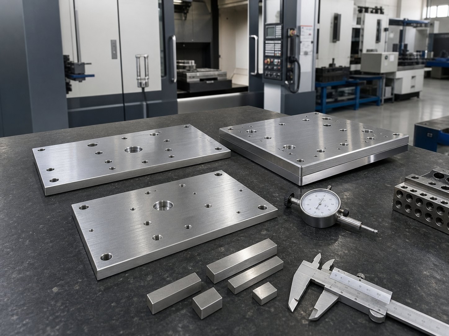
Summary:Flatness and parallelism depend on more than the final toolpath. Material stress, workholding, datum strategy, heat generation, feature sequence, and measurement conditions all affect the released part. OEMACHuses a staged review and machining approach for low-volume mounting plates, while confirming every project against its actual drawing and functional requirements.
Application Background
Mounting plates are widely used in automation systems, fixtures, precision instruments, and semiconductor equipment. They may combine mounting faces, locating holes, threaded holes, counterbores, pockets, and local steps.
Flatness controls the form of one surface, while parallelism controls orientation relative to a datum. Thickness readings alone do not fully establish either requirement.[Source: ISO 1101:2017]
Where individual dimensional or geometrical requirements are not stated, the drawing's general-tolerance framework and the functional needs of the assembly should be clarified before production.[Source: ISO 2768-1:1989][Source: ISO 2768-2:1989]
Key Machining Risks
• Residual stress may be released during roughing and part flipping.
• Excessive clamping can flatten a plate temporarily and conceal springback.
• Datum changes between operations can accumulate orientation error.
• Large pockets and dense hole patterns can reduce local rigidity.
• Surface texture and overall geometrical form describe different properties.[Source: ISO 21920-1:2021]
Process Recommendations
First identify functional faces, datum surfaces, locating features, and mating areas. If a hole or shaft uses a defined tolerance class, interpret it through the specified dimensional system rather than an assumed shop-fit practice.[Source: ISO 286-1:2010]
Use staged and relatively balanced stock removal. Rough both principal faces, allow the workpiece to stabilize when necessary, then proceed through semi-finishing and finishing. Support and clamping points should distribute force without forcing the plate into an artificial shape.
Plan pockets, holes, and precision faces as one process chain. Stable cutting tools, controlled heat input, clean support surfaces, and consistent measurement conditions help reduce variation. In-process checks can guide machining, but final verification should follow the drawing datum and the agreed part condition.
Service Process and Commitment
A practical workflow includes technical review, identification of functional surfaces, clarification of open items, process and workholding planning, first-piece confirmation, controlled production, process-check records, and protective packaging. OEMACH does not replace missing requirements with invented values and will request confirmation when a drawing condition affects machining or acceptance.
FAQ
Q1: Does a thickness tolerance automatically control parallelism?
No. Thickness is a size requirement; parallelism is an orientation requirement relative to a datum.[Source: ISO 1101:2017]
Q2: Why can a plate deform after unclamping?
Clamping may temporarily restrain residual stress or machining-induced distortion. The released condition therefore needs separate consideration.
Q3: Is grinding always required for tight flatness?
Not necessarily. Material, geometry, rigidity, batch size, surface needs, and available process capability should determine the route.
Q4: How can low-volume repeatability be improved?
Keep the datum strategy, fixture logic, tool sequence, and verification conditions consistent, and preserve first-piece and process-check records.
Q5: What information should be supplied for quotation?
Provide material and stock condition, geometry, functional datums, geometrical requirements, surface texture, quantity, assembly purpose, and delivery expectations. Open items should be listed for confirmation.
Scan to contact us
Contact: Allen
Email: shiziqiu@oemach.com
My whatsapp code