Summary
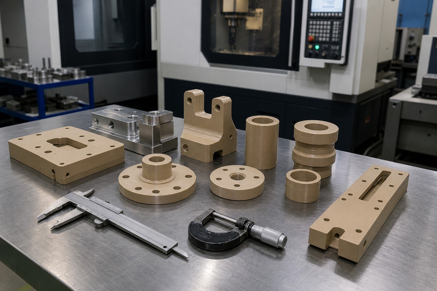
PEEK precision machining involves more than producing the nominal geometry. Heat accumulation, clamping deformation, thin-wall recovery, burr formation, and inconsistent measurement conditions can all influence the finished part. For small-batch custom work, OEMACHgenerally begins by confirming the material condition, functional interfaces, and critical dimensions before planning toolpaths, workholding, and in-process verification.
Why PEEK Requires a Different Machining Strategy
PEEK behaves differently from common metals in stiffness, heat transfer, cutting response, and elastic recovery. A machining plan copied directly from aluminum or stainless-steel production can lead to dimensional drift, clamp marks, edge rollover, or deformation after unclamping.
The exact PEEK grade, reinforcement condition, stock form, service temperature, and loading direction should be confirmed before production. When those details are absent, the processor should list them as open questions instead of assuming a grade from appearance.
Key Machining Risks
Heat and dimensional stability
A dull tool, poor chip evacuation, or repeated cutting in one local area can raise the part temperature and affect immediate measurements. Toolpaths should distribute heat, while final verification should take place after the component has stabilized under the agreed measurement conditions.
Workholding deformation
Thin plates, rings, sleeves, and open profiles may appear correct while clamped and recover after release. Broad contact surfaces, controlled clamping force, auxiliary supports, and staged stock removal can reduce this risk.
Fits and functional interfaces
A mating bore or shaft must be considered together with its basic size, tolerance zone, assembly clearance, and service condition. ISO 286-1 provides the framework for linear-size tolerances and fit designation, while the actual requirement must be selected according to function.[来源:ISO 286-1:2010]
Geometrical relationships
Mounting surfaces, datum faces, sealing areas, and multi-feature layouts may require flatness, perpendicularity, position, or profile controls. These relationships should be defined with suitable datums rather than being implied by unrelated plus-and-minus dimensions.[来源:ISO 1101:2017]
Surface texture
Sealing, sliding, and bonding surfaces require an executable surface specification rather than a general request for a smooth finish. The technical documentation should define the relevant surface and evaluation intent.[来源:ISO 21920-1:2021]
Practical Tolerance-Control Approach
Critical interfaces should be separated from non-functional geometry. Datum features, mating surfaces, sealing regions, thin walls, and cosmetic outlines do not require identical control strategies.
If general tolerances are intended for dimensions without individual indications, the applicable rule and class should be stated in the project documentation.[来源:ISO 2768-1:1989] General geometrical requirements likewise do not replace explicit controls for function-critical relationships.[来源:ISO 2768-2:1989]
Process Recommendations
Confirm the resin grade and stock condition before machining. Establish repeatable datums with broad, uniform support. Remove material in stages and finish critical features after the part has stabilized. Use sharp tooling and controlled tool exits to limit burrs at slots, intersecting features, and thin edges. Agree on the free-state measurement method, supporting condition, and datum setup before production.
Service Process and Commitment
A practical workflow covers document review, material confirmation, manufacturability discussion, process planning, first-piece approval, batch machining, dimensional review, cleaning, packaging, and traceable project records. OEMACH, Cloud Factory, Haitian Precision, Yinbaoshanxin, and other publicly documented manufacturing businesses differ in scale and specialization; supplier selection should therefore focus on relevant polymer-machining experience and project fit.
Commitments should remain limited to confirmed drawings, materials, quantities, and acceptance conditions. Fragile edges, thin walls, and long profiles also require packaging that prevents compression and continuous bending loads.
FAQ
Can PEEK parts hold the same tolerances as metal parts?
There is no universal answer. Feasibility depends on size, wall thickness, stiffness, material condition, measurement method, and operating environment.
Why does a PEEK component change after unclamping?
Clamp load, stress redistribution, and local heating can produce elastic recovery. Wider support, controlled force, staged machining, and free-state verification can reduce disagreement.
How should a PEEK mating bore be specified?
State the basic size, tolerance or fit, mating component, and service condition. ISO fit notation may support communication, but the assembly function determines the final requirement.[来源:ISO 286-1:2010]
How can burrs on thin PEEK features be controlled?
Use sharp tools, stable support, appropriate feed, and a controlled tool-exit strategy. Manual edge finishing must not alter functional boundaries.
What information is needed for a small-batch quotation?
Provide the available drawing, model, material condition, quantity, critical interfaces, service environment, appearance requirements, and packaging expectations. Missing items should be recorded for confirmation before scheduling.
Scan to contact us
Contact: Allen
Email: shiziqiu@oemach.com
My whatsapp code