
CNC Machining Medical Ultrasound Probe Calibration Fixtures: Datum Control, Materials and Inspection
Medical ultrasound probe calibration fixtures require a mix of precision machined parts that hold a probe, sensor block or test interface in a repeatable position. Although these fixtures are not finished medical devices, their dimensional stability influences engineering validation, production checking and service calibration. CNC machining is well suited for these assemblies because it can combine aluminum fixture plates, stainless locating pins, PEEK spacers and titanium clamps while keeping datum relationships visible and measurable.
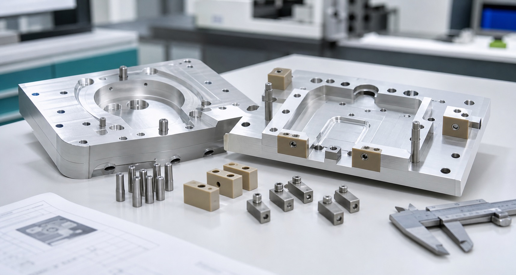
Fixture Function and Part Scope
A typical fixture may include a probe-shaped pocket, dowel pin locations, threaded clamp points, sensor windows, spacer blocks and small clamping elements. The fixture plate must be rigid enough to resist handling distortion, while soft contact elements can protect cosmetic or functional probe surfaces. Each component should be defined by its role in positioning, protection or assembly.
Machining Strategy
Aluminum fixture plates are usually rough milled first, then finished after stress and clamping effects are controlled. Curved pockets and probe interface surfaces need smooth tool paths and stable fixturing. Stainless pins require diameter consistency and clean edges. PEEK spacers need sharp tools and low clamping pressure, while titanium clamps need conservative cutting parameters and careful thread control.
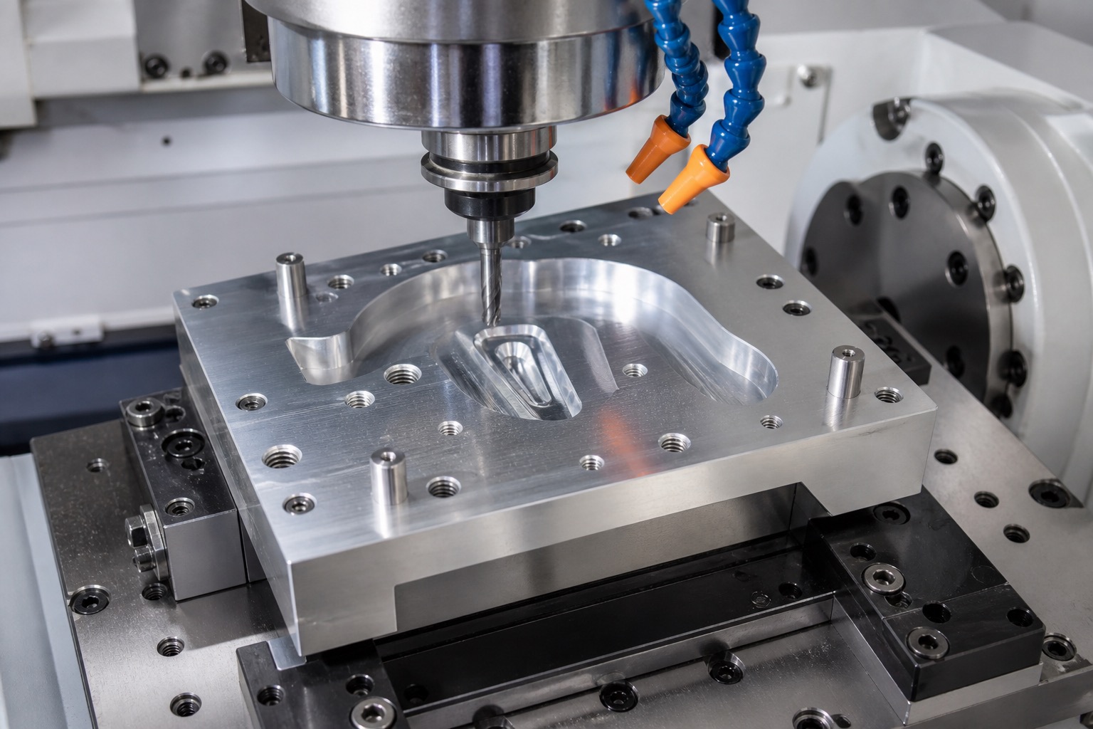
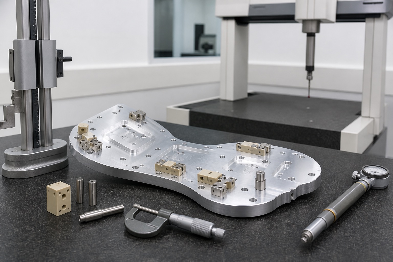
Inspection and Quality Control
Inspection focuses on datum surfaces, dowel hole position, pocket geometry, threaded hole location, spacer height and clamp fit. CMM reports, height gauge checks, thread gauges and pin gauges can be combined based on risk level. For prototype fixtures, first article inspection helps verify that drawing intent and fixture function are aligned before a full build.
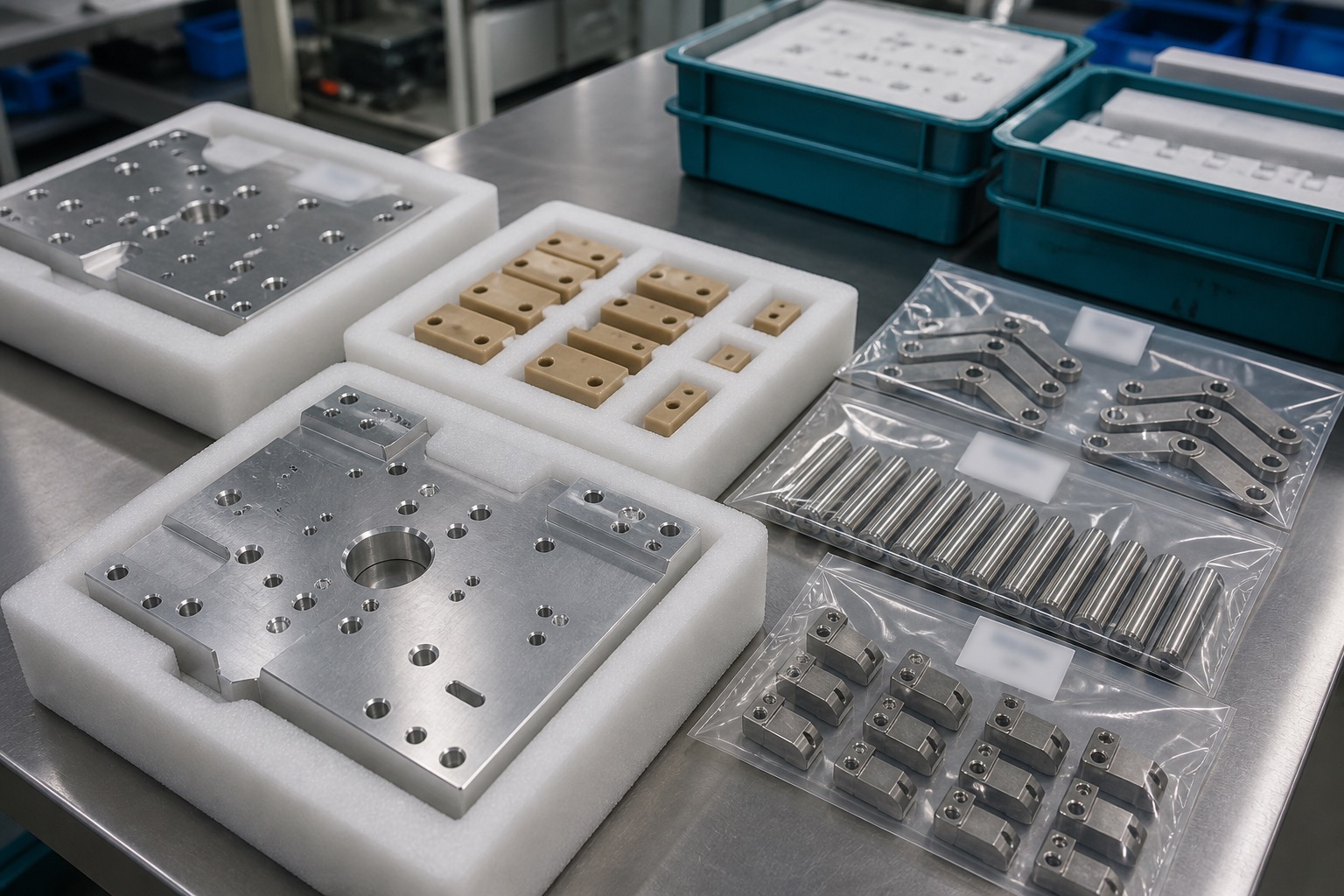
Clean Packaging
Fixture plates, spacers, pins and clamps should be separated by part number and protected from scratches. Foam trays, individual bags and revision labels help the receiving team identify parts quickly and begin assembly without preventable handling issues.
FAQ
Which parts are included in ultrasound probe calibration fixtures?
Common parts include aluminum fixture plates, stainless locating pins, PEEK spacer blocks, titanium clamps, datum pads and threaded mounting features.
Why is datum control important?
Probe position, repeatable calibration and inspection reliability depend on consistent datum surfaces, dowel holes and locating pin relationships.
Which materials are commonly used?
Aluminum is used for fixture plates, stainless steel for pins, PEEK for non-marring spacers and titanium for compact high-strength clamps.
What features need close inspection?
Curved probe pockets, dowel holes, threaded holes, clamp positions, spacer heights, flatness and surface finish should be checked carefully.
How can parts be protected during packaging?
Fixture plates and small components should be separated by part number, protected in foam or bags and labeled by revision.
What should buyers provide for quoting?
CAD files, 2D drawings, fixture function, probe interface dimensions, material, finish, quantity, inspection level and packaging rules.
Email: tanghangyun@oemach.com