
Optical lens mount machining needs coaxiality, face runout and assembly datums controlled together to prevent lens tilt and optical-axis drift.
In optical lens mount machining, lens mounting bore coaxiality and face runout are two specifications that are often underestimated. Bore diameter only tells whether a lens can fit. Coaxiality determines whether the lens center stays on the same optical axis, while face runout determines whether the seated lens is tilted.
Ordinary mechanical parts may only need clearance fit between holes and faces. Optical mounts are different. A slightly eccentric bore or a face with small runout can later appear as focal-plane drift, blurred image edges or repeated calibration adjustment.
OEMach usually starts by confirming the datum relationship among the lens, retaining ring, dowel pin holes and external mounting faces, then chooses 5-axis machining, mill-turn machining, dedicated soft jaws or CMM inspection to control the axis and face relationship.
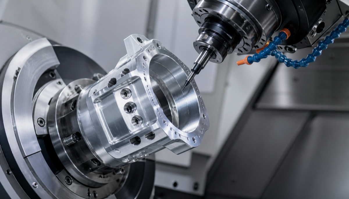
Coaxiality and Face Runout Control Table
This table is a useful first check during drawing review. The features that truly need tight control are the bores and faces inside the optical alignment chain, not every outside contour.
| Control item | Affected area | Common risk | Machining and inspection suggestion |
|---|---|---|---|
| Lens mounting bore coaxiality | Lens bore, step bore and retaining-ring bore | Lens center shifts and optical axis becomes unstable | Machine critical bores from one datum when possible; inspect by CMM or runout method |
| Face runout | Lens seating face and retaining-ring face | Lens tilts and focal plane drifts | Finish the face late in the process and evaluate it relative to the bore or assembly axis |
| Dowel pin holes | Repeatable location between mount and platform | Poor repeatability during optical alignment | Tie pin-hole position tolerance to the lens bore datum |
| Surface treatment | Anodized, blackened or matte surfaces | Bores become tighter and seating faces change condition | Reinspect critical bores and seating faces after finishing |
| Inspection datum | Machining datum, assembly datum and report coordinate system | Different parties get different results | State the coordinate setup and measured values clearly in the report |
Why Coaxiality Is More Than Bore Diameter
A lens mounting bore that meets diameter tolerance only proves that the assembly fit is roughly possible. An optical mount cares more about whether multiple bores, steps and external locating features share the same axis.
Coaxiality problems often appear after multiple flips, datum changes or thin-wall stress release. For example, if the outer profile is milled first and the lens bore is machined after a second setup, every individual size may pass while the optical-axis relationship has already shifted.
A stronger approach is to process the lens bore, retaining-ring step and key locating face in one setup or one unified coordinate system. Complex mounts can use 5-axis machining to reduce flips, or mill-turn machining to hold cylindrical axis relationships.
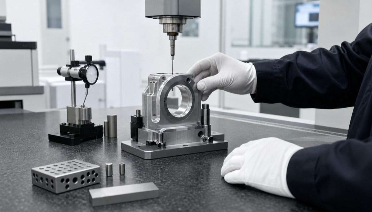
Face Runout Controls the Lens Seating Attitude
Face runout is not a replacement for flatness. Flatness describes whether a surface itself is flat. Face runout describes how that surface swings relative to a rotating axis or bore axis. Once the lens sits on the face, the face attitude becomes the lens attitude.
If face runout is too large, one side of the lens may contact first while the other side contacts later. The assembler may still clamp it with a retaining ring or shim, but optical calibration becomes less stable and temperature change can make the issue more obvious.
OEMach normally recommends leaving critical seating faces for late-stage finishing, controlling tool wear and cutting heat, and removing face burrs completely. Inspection reports should state whether the face is evaluated against the bore axis, outer diameter or bottom datum.
Put Machining and Inspection Into One Datum Logic
In one optical mount review, the original requirement focused mainly on lens bore diameter and outside dimensions. Drawing review showed that alignment was more affected by the relationship among the lens bore, retaining-ring face and bottom dowel pin holes.
The process route reduced datum changes with 5-axis machining, separated roughing and finishing for the lens bore and face, and applied a light final pass on the critical seating face. Inspection then built the coordinate system from the bottom assembly datum and reported lens-bore coaxiality, face runout and dowel-hole position.
After first-article assembly, lens tilt issues were reduced and pilot-batch consistency improved. The lesson is to manage machining, inspection and optical assembly as one system instead of checking only off-machine dimensions.
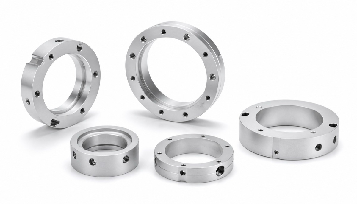
Five Items to Confirm Before RFQ
Confirm whether the lens bore, retaining-ring bore and external locating holes need to share one datum.
State whether face runout is evaluated relative to the bore axis, outer diameter or bottom datum.
Specify whether CMM, circular runout inspection or a dedicated gauge report is required.
Clarify whether critical bores and seating faces need reinspection after anodizing, blackening or blasting.
Record first-article optical assembly feedback so repeat orders can keep the same process logic.
For optical R&D teams, a supplier that can review datums, machine with 5-axis capability, inspect bore-axis relationships and recheck after surface treatment can reduce optical alignment rework.
Common Mistakes
The first mistake is checking only bore diameter tolerance while ignoring the bore-axis relationship. Optical mount bores serve the optical axis, not only assembly clearance.
The second mistake is treating flatness and face runout as the same item. They evaluate different relationships and should not be mixed.
The third mistake is accepting parts only because they passed machining inspection. Surface treatment, cleaning and clamping during assembly can still change critical seating conditions.
FAQ
Why does an optical lens mount need coaxiality control?
If the lens bore, retaining-ring bore and locating datum are not coaxial, the lens center can leave the optical axis and affect imaging or calibration stability.
Are face runout and flatness the same?
No. Flatness checks whether a face is flat. Face runout checks how that face swings relative to a bore axis or rotating axis.
How can lens mount coaxiality be inspected?
CMM, circular runout inspection or a dedicated gauge can be used. The key is matching the inspection datum with the assembly datum.
Should lens bores be reinspected after anodizing?
Critical lens bores, retaining-ring seats and seating faces should be reinspected after finishing because film thickness and surface condition can affect assembly.
Can OEMach machine optical lens mounts?
Yes. OEMach supports 5-axis machining, mill-turn machining, coaxiality inspection, face runout control and post-treatment reinspection for optical parts.
Summary
The challenge in optical lens mount machining is not a single bore diameter. It is whether lens bores, seating faces and locating datums work around one stable optical axis. Coaxiality and face runout should be inspected from the assembly datum, not judged only by off-machine dimensions.
Ready to get a quote for your CNC machined parts?
Submit your engineering drawings to qiancj@oemach.com. We support prototype sampling and small-batch production with strict tolerance control.