
Optical bracket machining depends on keeping machining, inspection and assembly datums aligned, while dowel pin design controls repeatable alignment.
Precision machining for optical brackets is not only about holding outer dimensions. The key is to keep machining datums, inspection datums and assembly datums aligned. A small error in a dowel pin hole, mounting face or perpendicular surface can shift lens posture and reduce imaging stability.
Dowel pin design is especially important. More pins do not automatically mean better accuracy, and placing pins at convenient corners may not control the optical function. Pin location, spacing, fit tolerance, assembly direction and inspection datum all affect repeatable alignment.
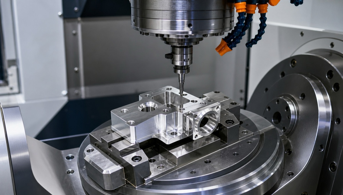
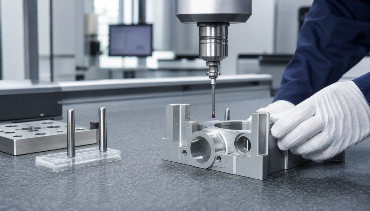
OEMach typically starts by confirming which face acts as the optical assembly datum and which holes control repeat location, then plans CNC machining, 5-axis setup reduction, CMM inspection and post-anodizing recheck around that logic.
Five Principles for Datum and Dowel Pin Design
| Principle | Design focus | Machining focus | Inspection check |
|---|---|---|---|
| Unify datums first | Keep assembly, machining and inspection datums as consistent as possible | Finish and protect critical datum faces early | Build CMM coordinates from assembly datums |
| Use one round pin and one slot | One round pin locates; one slot releases thermal and manufacturing variation | Define pin-hole size and slot direction clearly | Check hole spacing and orientation relationship |
| Place pins near functional zones | Locate near lens seat, detector or optical path | Reduce accumulated error from distant corners | Verify position to optical mounting features |
| Avoid weak edges | Do not place pins too close to thin walls or fragile edges | Prevent distortion and edge breakage | Check edge distance, burrs and hole-mouth quality |
| Recheck after finishing | Anodizing and blasting can affect fits | Mask or allow for coating thickness where needed | Use plug gauges or CMM after treatment |
Principle 1: Machining Datums Should Serve Assembly Datums
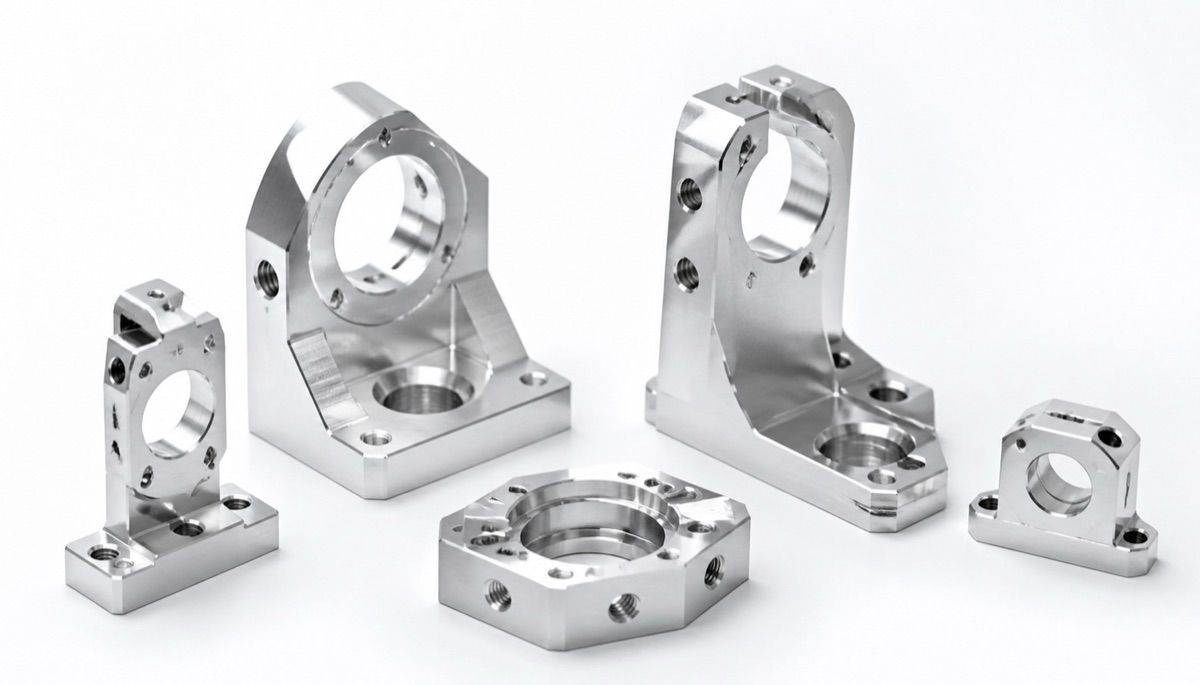
Optical brackets may hold barrels, lens seats, detectors, apertures or prisms. The important features are not usually the outside edges, but the faces and holes that establish the optical relationship.
If machining and assembly datums differ, the part can pass standalone dimensions and still create tilt, decenter or unstable repeat alignment in the system. Multi-face parts are especially sensitive because repeated refixturing can accumulate datum error.
A more stable process finishes the assembly datum face early, then machines dowel holes, optical mounting holes and perpendicular faces around that datum. Complex structures may benefit from 5-axis machining to reduce setups.
Principle 2: More Dowel Pins Are Not Always More Accurate
Adding more dowel pins can create overconstraint. During assembly, holes may compete for position, making the bracket hard to seat flat. Optical brackets should not rely on forceful assembly to solve alignment issues.
A common method is one round pin and one slot. The round pin gives accurate location; the slot limits direction while releasing manufacturing variation and thermal expansion. This improves repeatability without making assembly too tight.
If two round pins are far apart and both have tight fits, batch assembly can become difficult. Fit logic should be reviewed before machining.
Principle 3: Pins Should Be Close to the Optical Function
If dowel holes are far from the lens seat or detector mounting area, small errors can be amplified over the length of the bracket. This may be acceptable for ordinary mechanical supports, but it can disturb optical posture.
Pin placement should serve the optical function instead of only making the drawing look convenient. Two locating points near the optical mounting area often control real alignment better than two pins at distant outer corners.
During machining, dowel holes should be completed in a stable setup with the datum face. Hole-mouth deburring must also be clean so pins are not scratched and contact faces are not lifted.
Principles 4 and 5: Avoid Weak Edges and Recheck After Finishing
Dowel holes placed too close to thin walls, narrow ribs or fragile edges can distort during machining or chip during assembly. Edge distance, wall thickness and local stiffness should be evaluated before finalizing the drawing.
Surface treatment also matters. Anodizing, blasting and cleaning can change hole-mouth condition, coating thickness and final fit. Critical pin holes may need masking, allowance or post-treatment verification.
For optical brackets, inspection should include pin-hole position, flatness, perpendicularity and relationship to the optical mounting features, not only outer dimensions.
What to Confirm Before Ordering
Mark assembly datum faces, inspection datum faces and preferred machining datums on the drawing.
Decide whether the locating system uses one round pin and one slot or two round pins, based on assembly direction and thermal effects.
Specify the position of dowel pin holes relative to the lens seat, detector or optical functional area.
Review thin walls, narrow edges and post-anodizing pin fits before production.
Keep first-article data for pin holes, flatness, perpendicularity and assembly feedback so repeat orders can follow the same logic.
FAQ
Why is datum unity important for optical brackets?
If machining, inspection and assembly use different datums, a part can pass inspection but still create optical tilt or decenter in the system.
Are more dowel pins better?
No. Too many pins can overconstrain the part. One round pin plus one slot is often more practical for repeatable assembly.
Where should dowel pin holes be placed?
They should be close to the lens seat, detector or optical functional area to reduce error amplification.
Should pin holes be checked after anodizing?
Yes. Critical pin holes should be rechecked after finishing, and masking or coating allowance may be needed.
Can OEMach review optical bracket datums?
Yes. OEMach can help review datum faces, pin holes, GD&T and CMM inspection strategy for optical brackets.
Summary
Optical bracket machining depends on unified datums and practical dowel pin design. When datum faces, pin holes, GD&T, surface treatment and inspection are planned together, the bracket is more likely to support repeatable alignment and stable imaging.
Ready to get a quote for your CNC machined parts?
Submit your engineering drawings to qiancj@oemach.com. We support prototype sampling and small-batch production with strict tolerance control.