
±0.005 mm means ±5 microns on a defined feature, not a universal tolerance for every surface of a precision machined part.
In precision machining, ±0.005 mm means that a specific feature may vary by only five microns above or below its target dimension. That level is already demanding for CNC machining, workholding, tooling, temperature control and inspection.
The important point is that ±0.005 mm is usually a local functional requirement, not a whole-part default. It may be appropriate for bearing bores, dowel holes, precision steps, sensor mounting references, optical fits or key mating features. Applying it to every edge, pocket and cosmetic surface often raises cost and lead time without improving assembly.
OEMach typically reviews which dimensions truly affect function, then separates ±0.005 mm, ±0.01 mm, ±0.02 mm and general tolerances. This protects critical features while avoiding unnecessary high-precision work on non-functional areas.
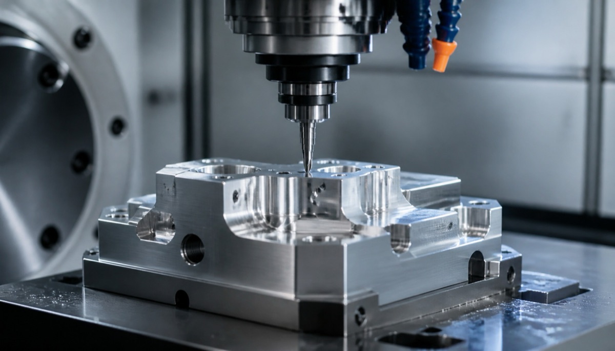
What Decides Whether ±0.005 mm Is Practical
| Factor | Favorable condition | Risk condition | Recommended approach |
|---|---|---|---|
| Part structure | Small, rigid part with concentrated critical features | Thin walls, long arms, large pockets or deep holes | Grade tolerances by function instead of tightening the whole part |
| Material | Stable aluminum, pre-treated steel or simple PEEK geometry | High internal stress, springback or thermal sensitivity | Separate roughing and finishing; consider stress relief where needed |
| Workholding | Critical datums completed in one stable setup | Multiple flips or weak locating faces | Use soft jaws, pins, vacuum holding or dedicated fixtures |
| Machining | Fresh tools, stable allowance and controlled heat | Tool wear, high cutting heat or uneven stock removal | Finish critical features last and track tool life |
| Inspection | CMM or dedicated gauges using the same datums | Inconsistent gauges or temperature differences | Provide first-article values and clear inspection datums |
Machine Accuracy Is Not the Same as Part Accuracy
A common misunderstanding is to read a machine tool's positioning accuracy as the finished part tolerance. The machine is only one part of the system. The part is also affected by clamping distortion, tool wear, cutting heat, material springback, refixturing error and inspection environment.
For example, a thin aluminum locating plate may be machined accurately while clamped. After release, it may spring back and shift key hole positions. A stainless steel miniature part may drift as tools wear and heat builds up. PEEK and other engineering plastics can move because of clamping pressure and temperature.
Stable ±0.005 mm delivery requires a process that accounts for these effects before the part is cut.
Where ±0.005 mm Belongs on a Drawing
Good candidates include features with clear function, limited size and measurable datum logic: bearing bores, dowel holes, optical barrel fits, sensor mounting planes, sliding grooves and precision reference steps.
Poor candidates include ordinary outside profiles, clearance pockets, weight-reduction cavities, cosmetic faces, large thin housings and non-contact contours. Tightening these areas often adds machining and inspection cost without improving the product.
A better drawing separates critical dimensions and GD&T from general features. This lets the supplier spend machining time, tool life and inspection effort where assembly performance depends on it.
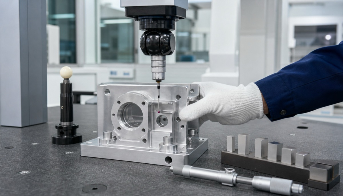
Where the Limit Usually Appears
The limit is rarely the machine alone. Material stress can change shape after cutting. Shop temperature can influence micron-level measurement. Tool wear can make dimensions drift during small batches. Inspection equipment and datum interpretation can produce different results if not defined.
For a local dimension on a small, rigid part, ±0.005 mm can often be evaluated under the right conditions. For complex thin-wall parts, large components, multi-face hole patterns or final dimensions after surface treatment, the difficulty rises quickly.
In some cases, grinding, wire EDM, honing, lapping or dedicated gauges may be needed. The better question is not simply whether ±0.005 mm is possible, but which feature, which material, how many parts, what inspection method and whether acceptance happens before or after surface treatment.
A Practical Tolerance-Grading Example
In one high-precision sensor mount review, the initial request applied ±0.005 mm broadly. After DFM review, the features were separated into three groups: sensor locating holes and datum faces were evaluated at ±0.005 mm, mounting holes were controlled at a practical tighter tolerance, and ordinary clearance profiles used general tolerances.
The process reduced refixturing, allowed stress release after roughing, finished critical holes last and measured hole spacing, flatness, perpendicularity and position with the assembly datum. The acceptance criteria became clearer for both machining and inspection.
This method keeps the important function protected while preventing non-functional surfaces from consuming unnecessary cost and lead time.
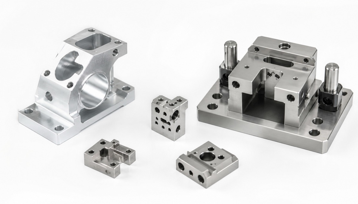
How to Write the RFQ
Place ±0.005 mm only on holes, slots, steps or mating faces that directly affect function.
Define inspection datums and measurement method together with the tolerance.
Clarify material, heat treatment, surface treatment and whether final inspection happens after finishing.
Ask the supplier to explain workholding and machining sequence for the critical features.
Request actual first-article measured values, not only a pass or fail statement.
FAQ
How many microns is ±0.005 mm?
±0.005 mm equals ±5 microns. It is a tight tolerance for defined critical features and usually needs stable workholding and reliable inspection.
Can CNC machining achieve ±0.005 mm?
Some critical features can be evaluated at this level when structure, material, workholding and inspection conditions are suitable. It does not mean every dimension of a part can be held that tightly.
Why not specify ±0.005 mm everywhere?
Whole-part tightening increases cost, inspection time and manufacturing difficulty. Many clearance or cosmetic features do not need that precision.
Does ±0.005 mm require CMM inspection?
For critical hole positions, flatness, perpendicularity and position tolerance, CMM or dedicated gauges are recommended with clear inspection datums.
Can OEMach support ±0.005 mm critical features?
Yes. OEMach can review feasibility, plan machining and provide CMM inspection and first-article reports for critical tolerance features.
Summary
±0.005 mm precision machining is best understood as five-micron control on selected critical features. The real limit depends on material, structure, workholding, heat, tooling and inspection. Functional tolerance grading is usually more effective than applying the same tight tolerance to the whole part.
Ready to get a quote for your CNC machined parts?
Submit your engineering drawings to qiancj@oemach.com. We support prototype sampling and small-batch production with strict tolerance control.