
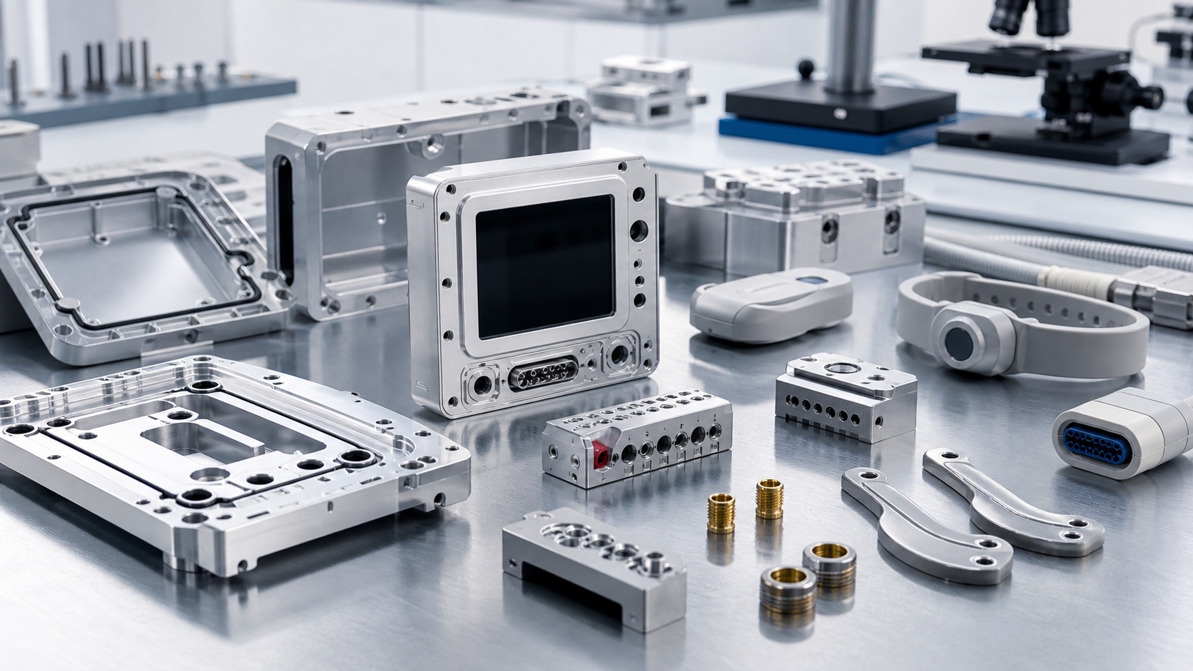
Technical guidance for CNC machining patient monitoring device housings, wearable sensor shells, connector blocks and probe brackets, covering thin-wall stability, gasket grooves, connector alignment, inspection and clean delivery.
Why Monitoring Device Housings Are More Than Cosmetic Parts
Patient monitors and wearable sensors rely on small mechanical components to protect electronics, guide cables, support probes and maintain sealing. A housing or connector block may look like an enclosure, but its flatness, screw bosses, gasket groove and connector alignment affect assembly quality and field reliability. CNC machining is useful for prototypes, pilot builds and low-volume production because it supports fast design changes, accurate pockets, threaded inserts, smooth edges and short lead times without hard tooling.
Material Options for Monitor and Sensor Components
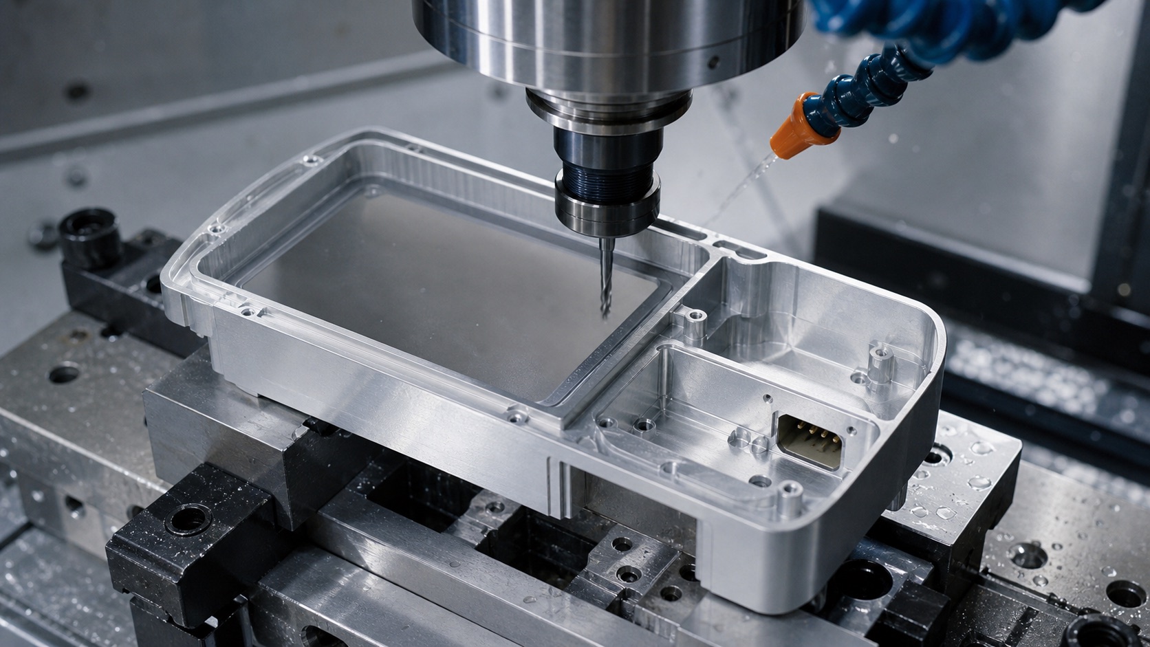
Common choices include 6061 aluminum, 7075 aluminum, stainless steel, PEEK, acetal and selected medical-grade plastics. Aluminum housings provide rigidity and good heat transfer, especially when anodizing is required. Stainless steel is often used for brackets, wear points and small connector details. Plastics help reduce weight and support electrical insulation. Before quoting, the drawing should clarify which surfaces are cosmetic, which surfaces are sealing or mounting datums and which areas must avoid scratches after finishing.
Thin-Wall Machining and Gasket Groove Control
Monitor housings often combine thin walls, display windows, cable openings and gasket grooves. Removing material too aggressively can release stress and change the fit of covers or seals. A stable machining process uses careful roughing, controlled clamping, semi-finishing and final finishing of gasket surfaces. Groove width, depth, corner radius and surface finish should match the sealing design. If the part will be anodized or coated, the effect of coating thickness on groove fit and threaded inserts should be considered early.
Connector Blocks, Probe Brackets and Cable Relief Features
Connector alignment is critical because repeated plug-in cycles can damage poorly positioned interfaces. ECG connector blocks, probe brackets and cable relief plates need accurate hole spacing, consistent thread quality and smooth lead-in edges. Small bracket parts may require multi-sided machining, thread milling, dowel holes and controlled deburring. For wearable sensors, rounded edges and low-profile transitions improve comfort and reduce the risk of snagging on straps or cables.
Inspection for Assembly and Reliability
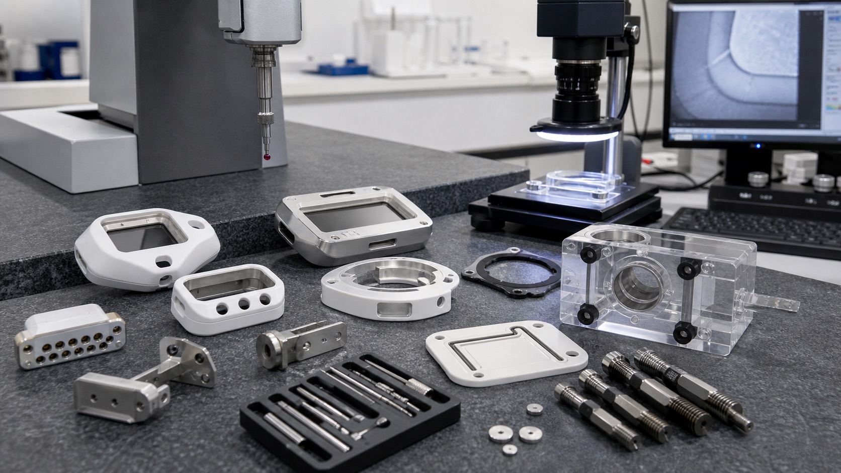
Inspection should cover flatness, hole position, display-window profile, gasket groove depth, connector position, thread quality, bracket perpendicularity and cosmetic condition. CMM inspection is useful for datum relationships, while microscopes and pin gauges help check small features. First article inspection can confirm whether the tolerance stack supports assembly before the design moves into a larger build. For parts that receive anodizing, passivation or polishing, inspection may be needed before and after finishing.
Clean Finishing, Packaging and RFQ Preparation
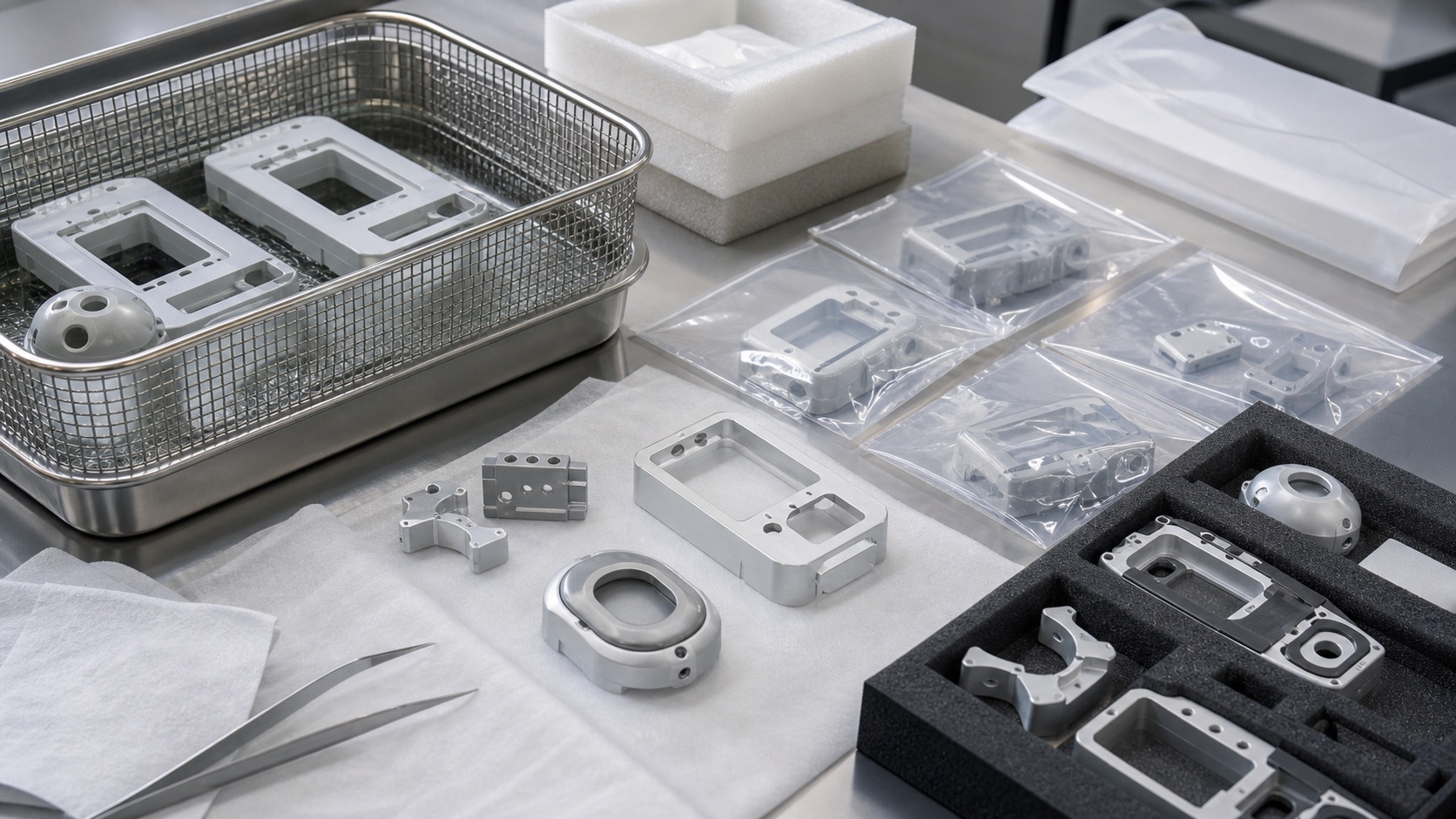
Medical monitor components often need controlled deburring, cleaning, anodizing, passivation, surface protection and individual packaging. Scratches on gasket surfaces or connector seats can create rework, so packaging should keep parts separated. Clean delivery does not replace the device maker's validated cleaning process, but it reduces incoming inspection problems. A strong RFQ should include CAD, 2D drawings, material and finish requirements, expected quantity, critical datum surfaces, gasket details, connector standards, inspection reports and packaging requirements.
FAQ
What files are needed to quote patient monitor housing parts?
A 3D CAD model, 2D drawing, material, finish, quantity, gasket details, connector standards and inspection requirements are the best inputs.
Which features should be marked as critical?
Mark gasket grooves, display-window faces, connector openings, threaded bosses, probe bracket datums and cable relief features that control assembly.
Can thin-wall aluminum monitor housings be CNC machined accurately?
Yes, but they require stable workholding, staged machining, stress control and final inspection of flatness and gasket features.
How are wearable sensor edges controlled?
Edges are controlled with programmed radii, chamfers, careful deburring and inspection so the component is smooth around straps, cables and skin-facing areas.
Should parts be inspected after anodizing?
Yes when coating thickness can affect gasket fit, threaded inserts, connector openings or cosmetic acceptance.
What packaging protects monitor components?
Individual bags, foam trays, surface protection film and separated small brackets help prevent scratches, thread damage and mixed revisions.
Email: tanghangyun@oemach.com