
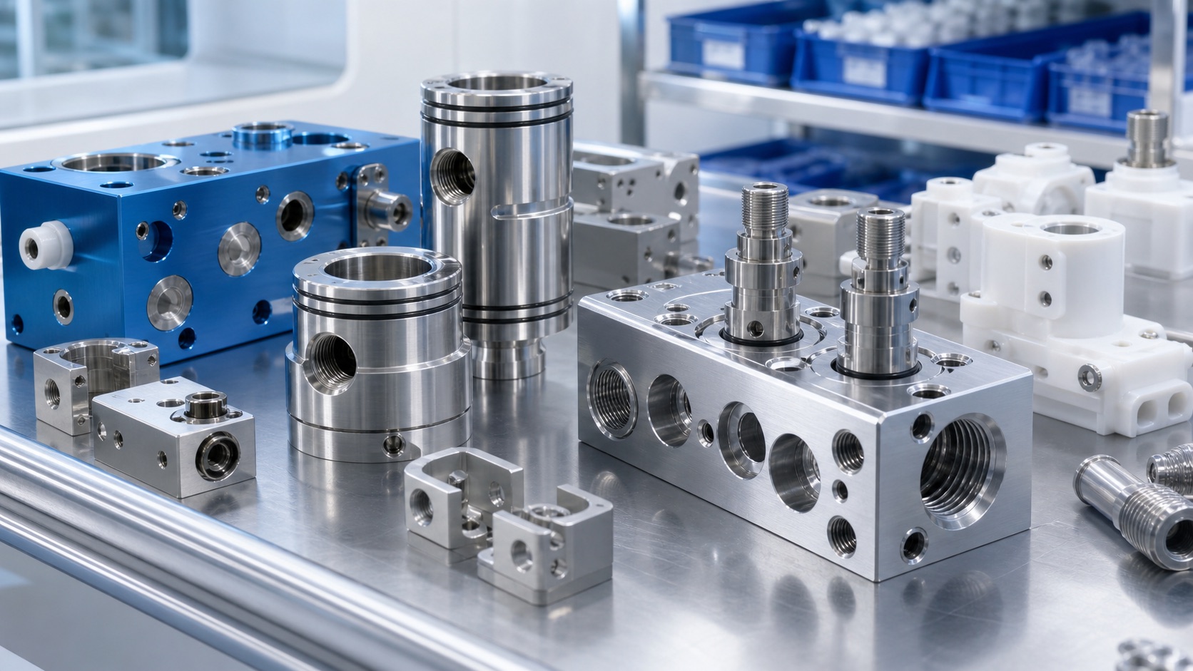
Technical guidance for CNC machining hemodialysis fluid manifold blocks, pressure sensor adapters and flow path components, covering sealing faces, cross holes, O-ring grooves, inspection and clean delivery.
Why Dialysis Fluid Path Parts Need Careful CNC Control
Hemodialysis equipment contains fluid management parts that must support stable flow, reliable sealing and repeatable assembly. Manifold blocks, valve housings, pressure sensor adapters and tube clamp brackets may look like ordinary machined components, but their ports, grooves and sealing faces directly affect leak risk and service reliability. CNC machining is suitable for prototypes and low-to-mid volume production because it can create accurate cross holes, threaded ports, O-ring grooves and compact mounting features while keeping design changes practical.
Materials for Manifolds, Fittings and Adapters
Common materials include 316L stainless steel, 304 stainless steel, anodized aluminum and selected medical-grade engineering plastics. Stainless steel is often used for fittings, sensor adapters and parts that require corrosion resistance. Aluminum is useful for lightweight housings or non-wetted structural blocks when finishing is specified. Plastics such as PEEK or acetal may be used for insulating or chemically compatible components. The RFQ should clearly state whether each feature is wetted, structural, cosmetic or only used for mounting.
Sealing Faces, O-Ring Grooves and Threaded Ports
Sealing faces and O-ring grooves are usually the most sensitive features. Surface finish, groove width, groove depth, corner radius and burr control all affect seal compression. Threaded ports must be clean and consistent so fittings install without galling or particle generation. Cross-drilled channels require a process plan that controls breakthrough burrs and verifies channel intersection. If the design uses plugs, inserts or press-fit sleeves, the drawing should define fit class, leak test needs and any no-scratch areas around sealing surfaces.
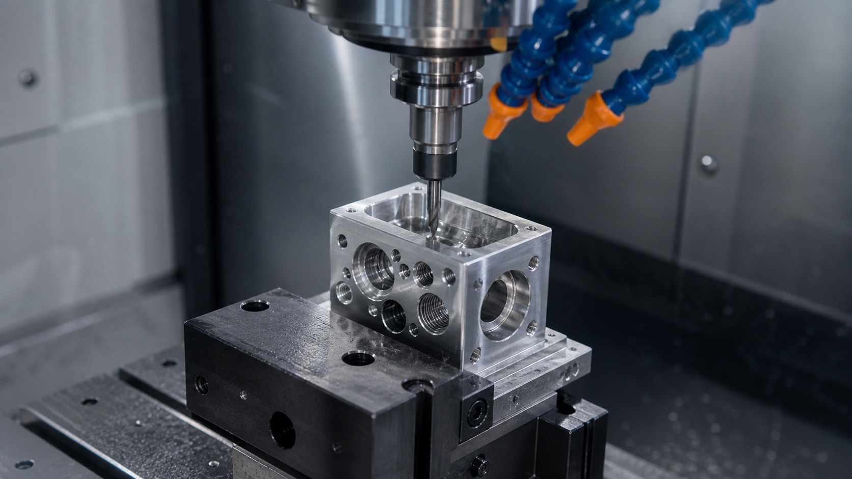
Machining Strategy for Cross Holes and Internal Features
Dialysis fluid blocks often require machining from multiple sides. A stable sequence starts with datum creation, then roughing, drilling, port threading, semi-finishing and final finishing on sealing or alignment features. Fixturing should protect finished faces and maintain location between operations. For small ports, peck drilling, thread milling and controlled deburring can reduce burr risk. Where possible, accessible channel intersections and practical radii help the supplier clean and inspect the part more reliably.
Inspection and Leak-Related Quality Checks
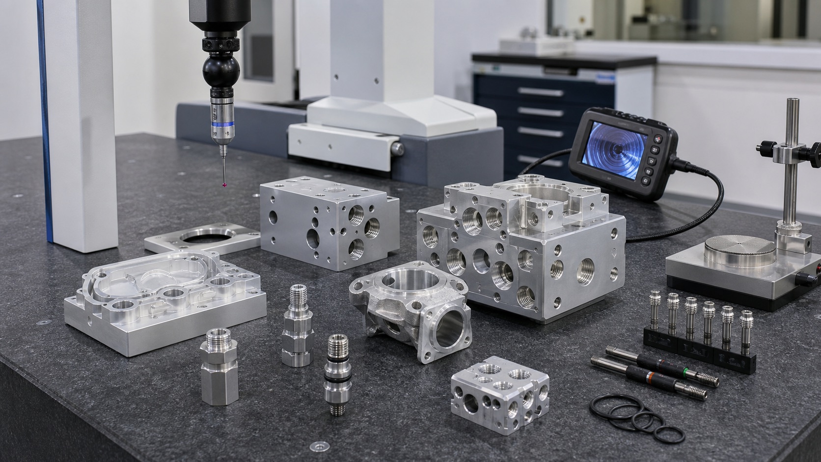
Inspection may include CMM checks, thread gauges, pin gauges, bore inspection, surface roughness review and visual inspection under magnification. For fluid path components, measurement is only part of the story: suppliers may also need to support pressure decay, flow confirmation or customer-defined leak test preparation. First article reports are especially useful for confirming groove dimensions, port positions and datum relationships before scaling the design. Traceability of material, revision and inspection records helps engineering teams isolate changes quickly.
Clean Finishing, Packaging and RFQ Information
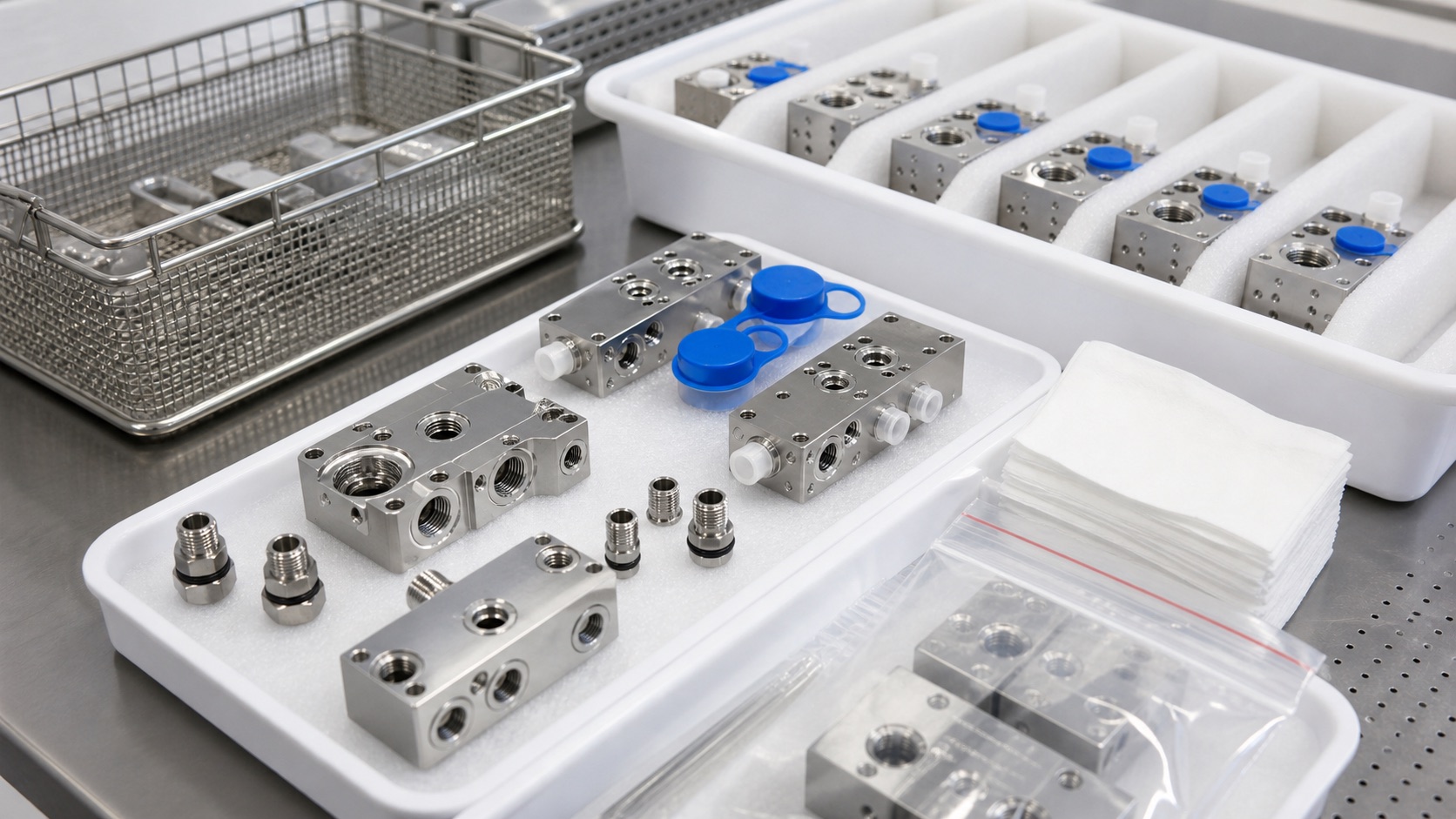
After machining, fluid path components often need controlled deburring, passivation for stainless steel, cleaning, drying and protective packaging. Sealing faces should be protected from scratches, and small fittings should be separated to avoid thread damage. Clean delivery does not replace the device maker's validated cleaning process, but it reduces contamination and handling risk before incoming inspection. A strong RFQ should include CAD, drawings, material and finish requirements, port standards, O-ring details, critical dimensions, inspection reports, quantity and packaging rules.
FAQ
What files are needed to quote dialysis fluid manifold parts?
A 3D CAD model, 2D drawing, material grade, port standard, O-ring details, quantity and inspection requirements are the best starting inputs.
Which features should be marked as critical?
Mark sealing faces, O-ring grooves, threaded ports, cross-hole intersections, sensor adapter bores and datum surfaces that control assembly.
How are burrs controlled inside cross-drilled channels?
Burrs are controlled with process sequencing, sharp tools, peck drilling, deburring access planning, borescope checks and customer-defined cleanliness criteria.
Can stainless steel dialysis fittings be CNC machined in small batches?
Yes. CNC turning and milling are suitable for prototype and low-volume stainless fittings, especially when thread quality and sealing surfaces are critical.
When is passivation useful?
Passivation is often specified for stainless steel parts after machining to improve corrosion resistance, subject to the device maker's material and process requirements.
What packaging protects fluid path components?
Individual wrapping, port caps, foam separation, clean bags and clear labels help protect threads, sealing faces and traceability during shipment.
Email: tanghangyun@oemach.com