
Flatness and perpendicularity on optical structural parts should be controlled around optical datums, not tightened blindly across the whole part.
Optical instrument structural parts often require tighter flatness and perpendicularity than ordinary mechanical brackets. The reason is not that every surface must be ultra-precise. The real issue is that selected mounting faces become part of the optical datum chain.
A general machine bracket may work with flatness around 0.05 mm to 0.10 mm in many assemblies. A lens mount, detector bracket, aperture seat or collimator support may need selected datum faces evaluated around 0.005 mm to 0.01 mm, depending on part size, material, function and inspection method.
OEMach first identifies the role of the part in the optical path. Then the drawing is separated into optical datums, functional mounting faces and non-contact clearance areas so only the surfaces that influence alignment are tightened.
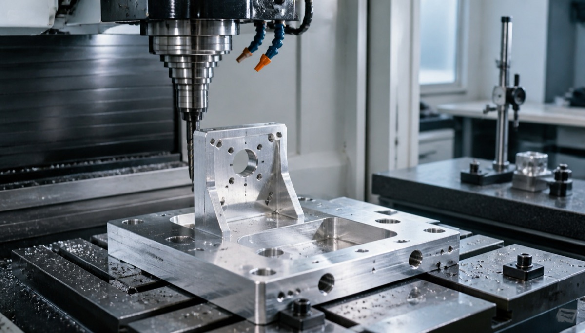
Where Optical Parts Differ From Ordinary Mechanical Parts
| Item | Ordinary mechanical part | Optical structural part | RFQ confirmation |
|---|---|---|---|
| Mounting plane | Often accepted by general assembly fit | Critical faces may need much tighter flatness | Is the face a lens, detector or optical-path datum? |
| Perpendicularity | Usually judged by mechanical fit | Can affect optical-axis angle and focal-plane posture | Define perpendicularity relative to the assembly datum |
| Inspection method | Calipers, height gauge or surface plate may be enough | CMM, granite plate, optical tools or dedicated fixtures may be needed | State datum setup and measured values |
| Machining route | Conventional milling may be sufficient | Low-stress fixturing, rough/finish separation and reduced re-clamping matter | Review datum drift and deformation risk |
| Surface treatment | Often accepted by corrosion or appearance | Post-finish contact surfaces may need review | Confirm masking, film allowance and post-treatment inspection |
Why Small Posture Errors Become Optical Errors
In ordinary hardware, unstable flatness may create a gap, local stress or visible mismatch. In an optical structure, the same geometric error can tilt a lens, move a detector plane or change the relationship between an aperture and the designed optical axis.
Perpendicularity is similar. If the side wall of a bracket is not square to the base, the attached sensor may look mechanically fixed while its sensitive plane is already tilted. Later correction by shims, adhesive or adjustment screws takes time and can reduce batch consistency.
For this reason, optical structural parts should not be judged only by outside dimensions. Key planes, locating holes, end faces and optical datums need to be evaluated in a shared coordinate system that reflects how the part is actually assembled.
Machining Starts With Fixturing and Stress Control
Common materials include aluminum alloys, stainless steel and engineering plastics such as PEEK. Aluminum supports lightweight structures and anodized appearance, but large cavities, thin walls and one-sided stock removal can create deformation. Stainless steel is rigid but more sensitive to burrs and tool wear. PEEK requires attention to clamping pressure and thermal rebound.
A stable process normally separates roughing and finishing, removes stock symmetrically, uses low-stress clamping and applies light finishing cuts on critical faces. Complex parts may benefit from 5-axis machining to reduce re-clamping, while thin plates may need soft jaws, vacuum support or temporary process ribs.
If black anodizing, blasting or black oxide is required, the team should decide whether contact datums and locating holes are masked, whether coating thickness affects the final dimension, and whether post-finish inspection is required.
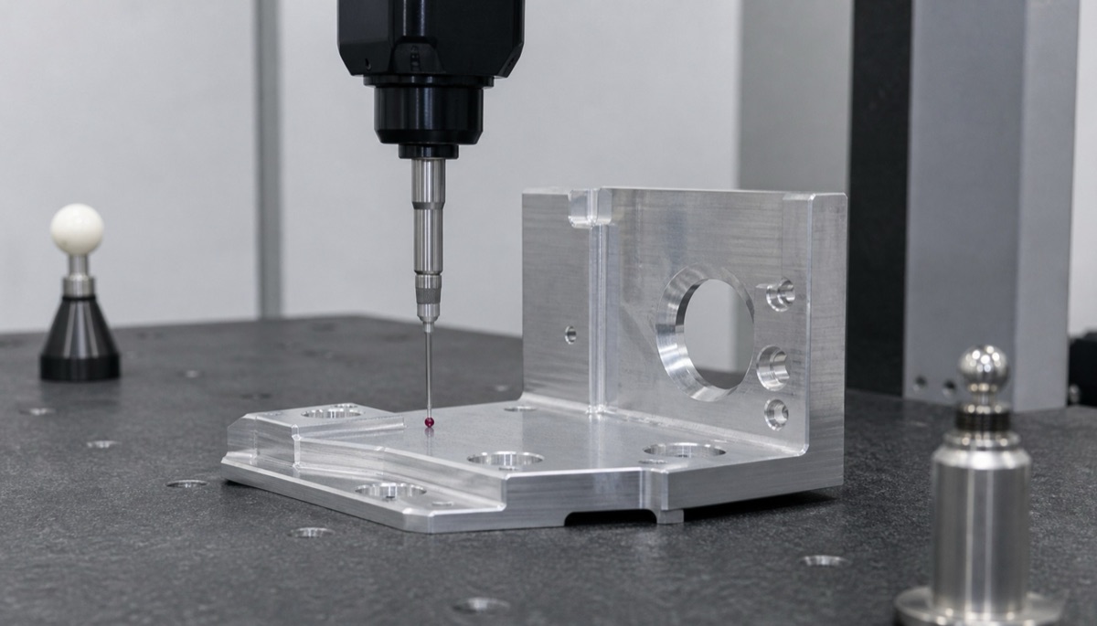
Practical Review: Merge Machining, Inspection and Assembly Datums
In an optical detector bracket review, the initial discussion focused only on bottom-face flatness. After DFM review, the more important issue was the perpendicular relationship among the base, side locating face and detector mounting plane.
The process reduced re-clamping, separated rough and finish cuts on the base and side wall, and used light finishing passes on the critical planes. CMM inspection was then built from the assembly base datum rather than from a convenient machining feature.
This kind of datum alignment makes the acceptance result more useful. The inspection report describes the relationship that matters to optical alignment, not only whether one isolated surface looks flat on its own.
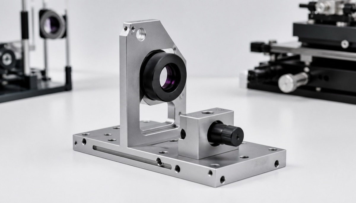
What to Confirm Before Ordering
Mark optical datum faces, general mounting faces and non-contact clearance surfaces separately. Avoid applying the tightest flatness to every surface.
Define which plane, hole or coordinate system controls flatness and perpendicularity.
Confirm whether CMM data, flatness reports or post-treatment reinspection are required before quotation.
For thin-wall or large-area parts, review clamping deformation, material stress and surface-treatment effects early.
Keep first-article measured values and assembly feedback so repeat orders follow the same acceptance logic.
FAQ
Why do optical structural parts need tighter flatness?
Flatness can influence the posture of lenses, detectors or apertures. Small errors may be amplified by the optical path and create focus or alignment instability.
Does every optical part surface need 0.005 mm flatness?
No. Tight flatness should be reserved for optical datums, contact faces and critical mounting surfaces. Clearance areas should not be tightened blindly.
How should perpendicularity be inspected?
The drawing should state the reference datum. For critical parts, inspection should use the same datum system used in final assembly.
Should parts be inspected after anodizing?
Key holes, contact faces and optical datums should usually be reviewed after anodizing, blasting or cleaning because the final surface state can affect assembly.
Can OEMach help review optical flatness requirements?
Yes. OEMach can support DFM review, low-stress CNC machining, CMM inspection and post-finish checks for optical structural parts.
Summary
Optical instrument structural parts need tight flatness and perpendicularity where those surfaces enter the optical datum chain. The practical goal is not to make every face extreme, but to connect optical function, machining datum, inspection datum and surface treatment into one controllable process.
Ready to get a quote for your CNC machined parts?
Submit your engineering drawings to qiancj@oemach.com. We support prototype sampling and small-batch production with strict tolerance control.