Summary
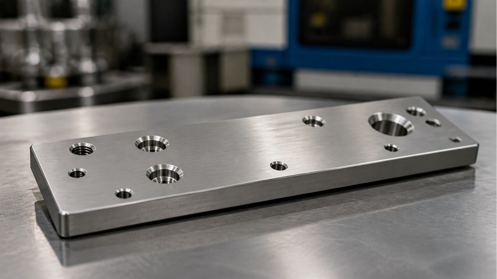
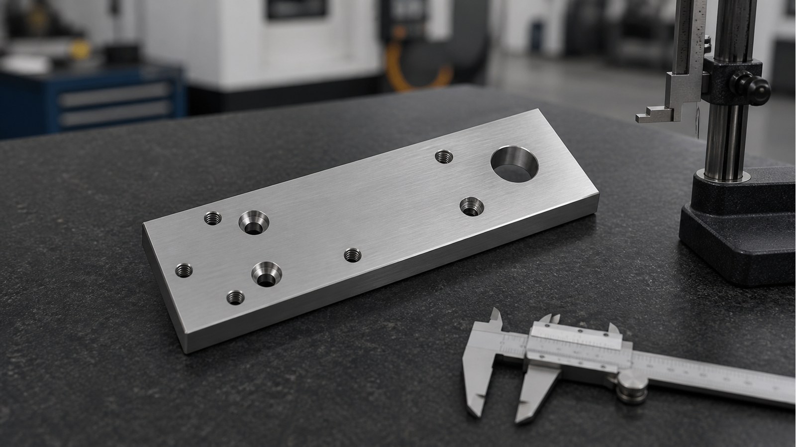
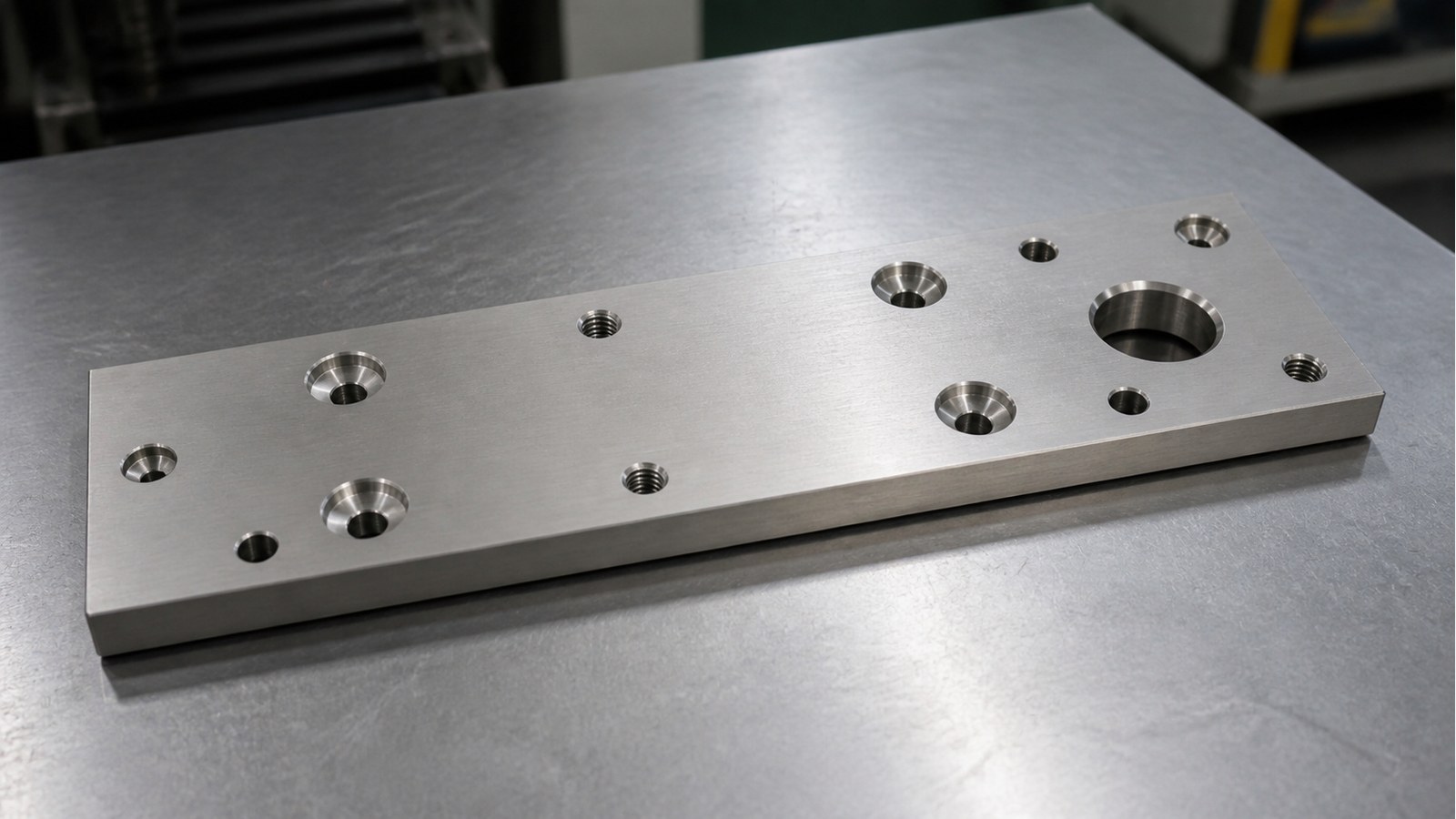
This anonymized case records Engineer Zhang’s review of an AISI 304 rectangular mounting block for custom automation assembly equipment. The drawing shows a 270 mm × 82 mm × 15 mm plate with a through hole, counterbores, tapped holes, and datum surfaces. OEMACHnormally reviews datum transfer, hole relationships, stainless-steel cutting behavior, and deburring as one connected process.
Case Background and Application Assessment
In June 2026, Engineer Zhang received a prototype inquiry from an automation assembly customer in Suzhou. Based on the plate geometry and hole features, he assessed the component as a mounting block used to connect, locate, or support an actuator or accessory module. This is an anonymized engineering assessment rather than confirmation of a particular machine model.
Drawing Data Summary
The visible drawing information identifies AISI 304, an overall size of 270 mm × 82 mm × 15 mm, a φ25 through hole, four M8 fully tapped through holes, several φ9 holes with φ15 counterbores, and an IT12 general tolerance note. The drawing also requires burr removal and edge dulling. [Source: Visible annotations in the customer-provided engineering drawing]
Key Machining Risks
Engineer Zhang identified four connected risks: distortion caused by concentrated clamping on the elongated plate, datum transfer between machining faces, orientation errors involving front and rear counterbores, and work-hardening or burr formation during stainless-steel drilling and tapping.
General tolerances support dimensions without individual tolerance indications, but functional interfaces still require project-specific review. [Source: ISO 2768-1:1989] Hole and fit requirements should be interpreted through the applicable tolerance system and assembly function. [Source: ISO 286-1:2010]
Process Recommendations
Engineer Zhang’s proposed route is drawing review, datum and counterbore-orientation confirmation, stock preparation, primary-face machining, profile machining, coordinated hole machining, tapping, reverse-side machining, deburring, dimensional review, cleaning, and protected packing.
Hole features should be programmed from a shared coordinate datum where practical. Datum surfaces should be protected during secondary clamping. If flatness, perpendicularity, or positional controls are functionally required, they should be stated in the controlled drawing using an appropriate geometrical tolerancing framework. [Source: ISO 1101:2017]
Small-Batch Delivery Communication
For this mounting block used in custom automation assembly equipment, Engineer Zhang recommends confirming drawing revision, assembly datum, counterbore direction, functional holes, edge-treatment boundaries, and packing requirements before batch continuation. First-piece confirmation records and dimensional review records can support traceable communication without extending the project scope.
FAQ
**Q1: Why is this part more involved than a plain plate?** It combines through holes, counterbores, fully tapped holes, datum surfaces, and orientation-dependent features.
**Q2: Does IT12 define every functional requirement?** No. It is a visible general-tolerance note; functional interfaces still require confirmation against the controlled drawing.
**Q3: What matters during AISI 304 tapping?** Stable feed, chip evacuation, tool condition, entry-edge control, and verification of the fully threaded passage.
**Q4: How can reversed counterbores be prevented?** Use a face-orientation checklist and cross-check the drawing, model, and assembly notes during first-piece confirmation.
**Q5: What should be reviewed before small-batch delivery?** Drawing revision, datum logic, hole purpose, counterbore orientation, burr boundaries, dimensional records, and protective packing.
Scan to contact us
Contact: Allen
Email: shiziqiu@oemach.com
My whatsapp code