
Surface roughness on robot machined parts should be specified by function, not made equally smooth on every surface.
Surface roughness for robot machined parts is not a contest to make every face mirror smooth. The better approach is to decide what each surface does in the assembly, then assign a realistic Ra requirement to that function.
Bearing bores, dowel holes, sliding contact areas, sealing faces, sensor mounting planes, cosmetic covers and internal weight-reduction pockets do not need the same finish. A drawing that applies Ra 0.8 to the whole part may look strict, but it can add machining time, tool wear, polishing work and inspection cost without improving the robot assembly.
OEMach reviews roughness together with tolerance, GD&T, burr control, surface treatment and inspection method. This helps engineers specify tighter finishes where function depends on them, while leaving non-critical surfaces manufacturable and cost-effective.
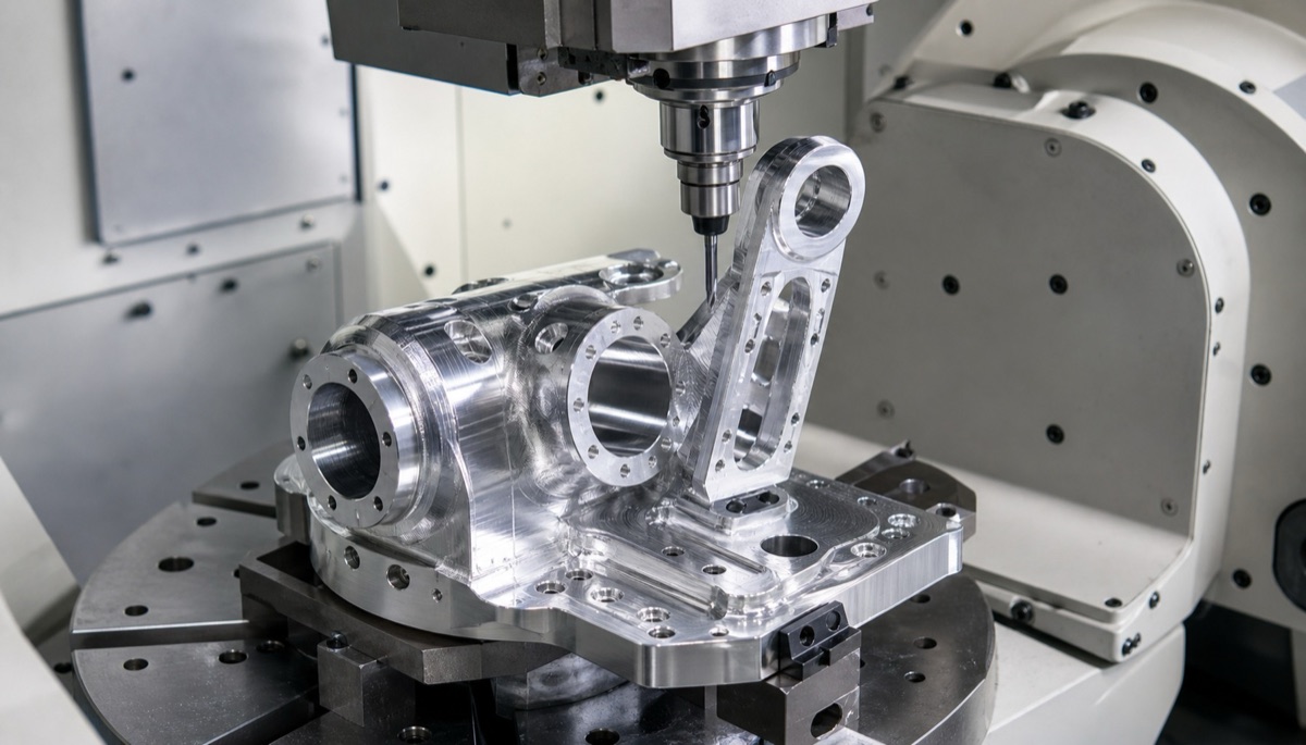
Recommended Roughness Zones for Robot Parts
| Surface type | Typical roughness | Common locations | What to verify |
|---|---|---|---|
| Bearing and locating bores | Ra 0.4 to Ra 0.8 | Joint bearing seats, dowel holes, precision bush bores | Bore size, roundness, coaxiality, burrs and measured Ra |
| Mounting and datum faces | Ra 0.8 to Ra 1.6 | Motor covers, sensor seats, IMU mounts, gearbox interfaces | Flatness, perpendicularity, edge breaks and post-finish condition |
| Sliding or wear faces | Ra 0.4 to Ra 0.8, or by friction pair | Guide blocks, sliding pads, wear contact areas | Material pair, lubrication, coating or hardening requirements |
| Cosmetic and anodized faces | Ra 1.6 to Ra 3.2 before blasting or as agreed | Visible aluminum brackets and covers | Tool mark direction, blasting, color consistency and scratch criteria |
| Clearance and lightening pockets | Ra 3.2 or machined finish | Internal cavities, relief pockets, non-contact surfaces | Avoid unnecessary tightening that raises cost and lead time |
Why Smoother Is Not Always Better
Lower Ra values usually require slower finishing passes, sharper tools, smaller stepovers, boring, grinding, polishing or additional handling. For a non-critical pocket, this can make the part more expensive without changing fit, strength or motion performance.
Some functional surfaces also need the right texture rather than the lowest possible number. A sliding surface may rely on lubrication behavior. A bonding or coating surface can lose adhesion if it is over-polished. A blasted anodized surface can still look inconsistent if tool marks and grain direction were not controlled before finishing.
That is why roughness should be connected to function. Robot parts normally deserve strict control on bearing seats, locating holes, datum faces, sensor interfaces and moving contact areas. Clearance surfaces and hidden pockets should be specified only as tightly as the application requires.
Roughness Must Be Reviewed With Tolerances and Burrs
Ra alone does not guarantee assembly quality. A bearing bore with a good surface finish may still fail if roundness, bore size or coaxiality is unstable. A bright mounting face may still stress a sensor or motor cover if flatness is poor.
Burrs are another practical issue. Hole mouths, cross holes, thin edges, milled slots and thread starts can feel rough in assembly even when the measured Ra value is acceptable. For robot prototypes and small batches, roughness notes should be reviewed together with chamfers, deburring, cleaning and inspection datums.
Material and finishing route also matter. Aluminum parts may change after anodizing or blasting, stainless steel can show tearing if tools are worn, and engineering plastics such as PEEK may need a different burr-control strategy from metals.
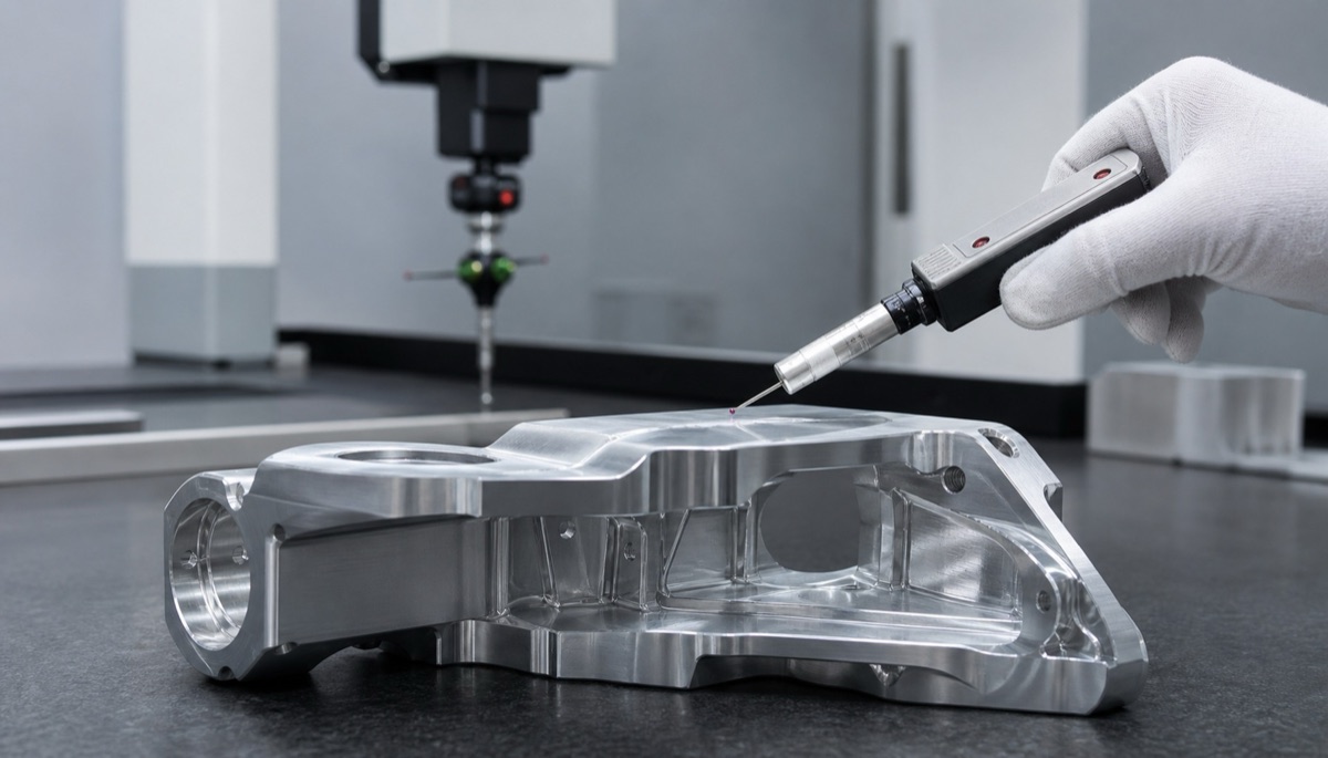
A Practical DFM Review Method
In one robot joint component review, the initial requirement treated the whole part as a high-finish item. After the functional surfaces were separated, the key bearing bore was held to a tighter Ra range with bore and roundness inspection, the mounting face used a practical Ra and flatness requirement, and internal lightening pockets were accepted as machined surfaces.
This did not weaken the specification. It made the specification clearer. The machining team knew where to spend time, the inspection team knew which surfaces required measured records, and the buyer avoided paying for unnecessary finishing on hidden areas.
For repeat orders, OEMach keeps first-article inspection data, roughness notes, toolpath decisions and finishing requirements together so the next batch can follow the same logic instead of restarting the discussion from a vague global Ra callout.
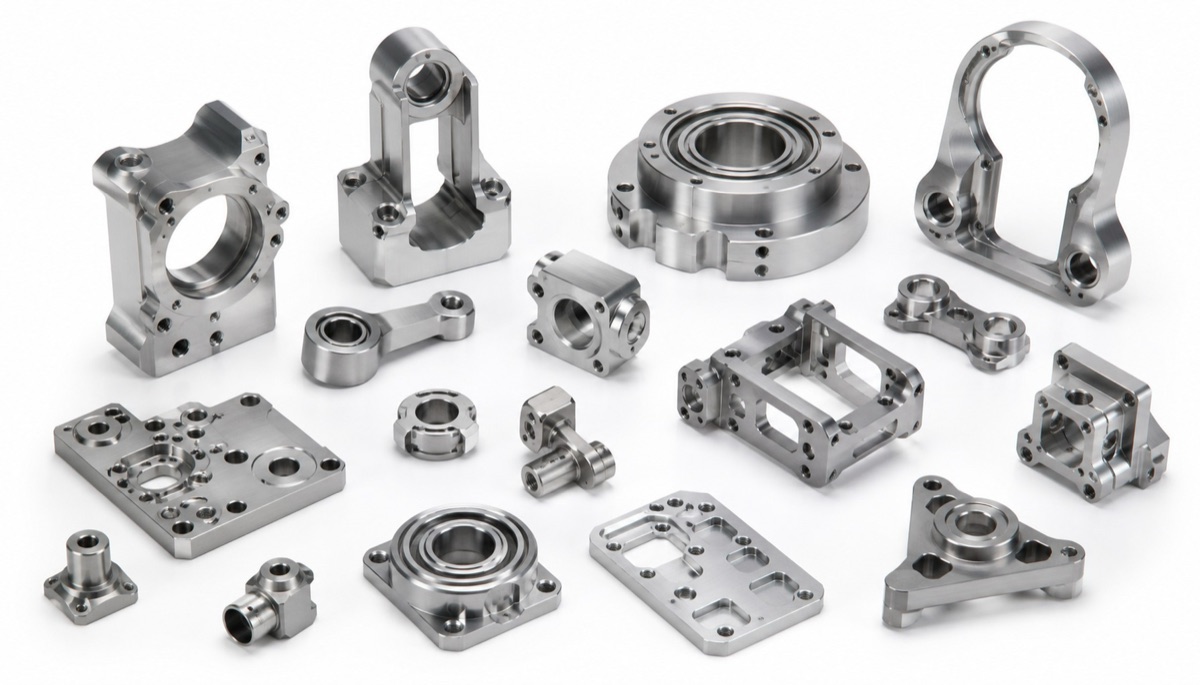
What to Mark Before Sending an RFQ
Separate functional surfaces on the drawing: locating, rotating, sliding, sealing, mounting, cosmetic and clearance surfaces should not share one blind roughness note.
Place Ra requirements next to the related tolerance and GD&T callouts, especially for bearing bores, dowel holes, datum planes and sensor mounting faces.
Clarify whether roughness is accepted before or after anodizing, blasting, plating, heat treatment or polishing.
For critical faces, state measurement position and direction so the inspection result reflects how the surface works in assembly.
When a surface is not function-critical, avoid over-specifying it. The saved machining time can be better used on the surfaces that actually control robot performance.
FAQ
Should every robot machined part use Ra 0.8?
No. Ra 0.8 can be useful on selected functional surfaces, but clearance pockets and many cosmetic surfaces often do not need that level of control.
What roughness is typical for robot bearing bores?
Many bearing or locating bores use Ra 0.4 to Ra 0.8, but bore size, roundness, coaxiality and burr control are just as important.
How should anodized aluminum surfaces be specified?
Define the desired final appearance and acceptance stage. Tool marks, blasting, anodizing thickness, masking and scratch criteria may matter more than one isolated Ra value.
Can roughness affect robot assembly?
Yes. Surface texture can affect bearing fit, sliding behavior, sealing, sensor seating, coating adhesion and the way a part feels during assembly.
Can OEMach help define roughness requirements?
Yes. OEMach can review drawings and help separate functional surfaces, practical Ra values, deburring notes and inspection requirements before machining.
Summary
Surface roughness for robot machined parts should be specified by function. Tighten Ra where bearing fit, sliding, sealing, datum contact or sensor mounting depends on it, and keep non-critical surfaces practical. A clear roughness strategy reduces unnecessary cost while making the important surfaces easier to machine, inspect and repeat.
Ready to get a quote for your CNC machined parts?
Submit your engineering drawings to qiancj@oemach.com. We support prototype sampling and small-batch production with strict tolerance control.