
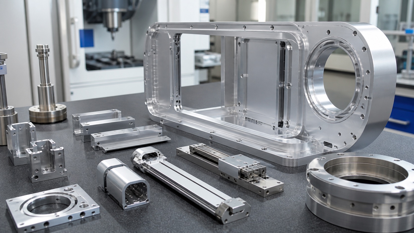
Technical guidance for CNC machining medical imaging equipment detector housings, positioning slides and collimator brackets, covering stability, datum control, thin-wall frames, inspection and clean delivery.
Why Imaging Equipment Components Need Stable CNC Processes
Medical imaging equipment depends on repeatable mechanical alignment. Detector housings, collimator brackets, guide rail carriers and positioning slides may not contact the patient, but they influence how accurately sensors, optics, shielding and motion modules are held in place. A slight shift in flatness, perpendicularity or datum location can create assembly drift, rework or calibration time. CNC machining is valuable because it can produce low-volume and mid-volume components with controlled pockets, dowel holes, threaded features and edge quality while keeping design changes practical during equipment development.
Material Choice for Detector Housings and Brackets
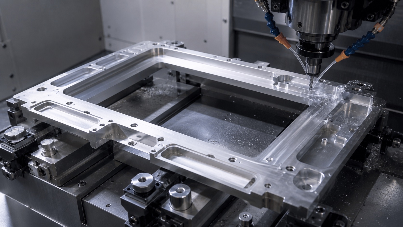
Common materials include 6061 or 7075 aluminum for lightweight frames, stainless steel for wear or shielding-related brackets, and engineering plastics for insulating covers or cable guides. Aluminum detector frames often require anodizing, so machining allowance and surface preparation should be considered before finishing. Stainless steel brackets need tool control to prevent work hardening and burrs in small holes. When the part holds sensors, guide rails or collimator elements, the drawing should separate cosmetic surfaces from functional datum faces so the supplier can protect the areas that matter most.
Thin-Wall Frames, Pockets and Cable Channels
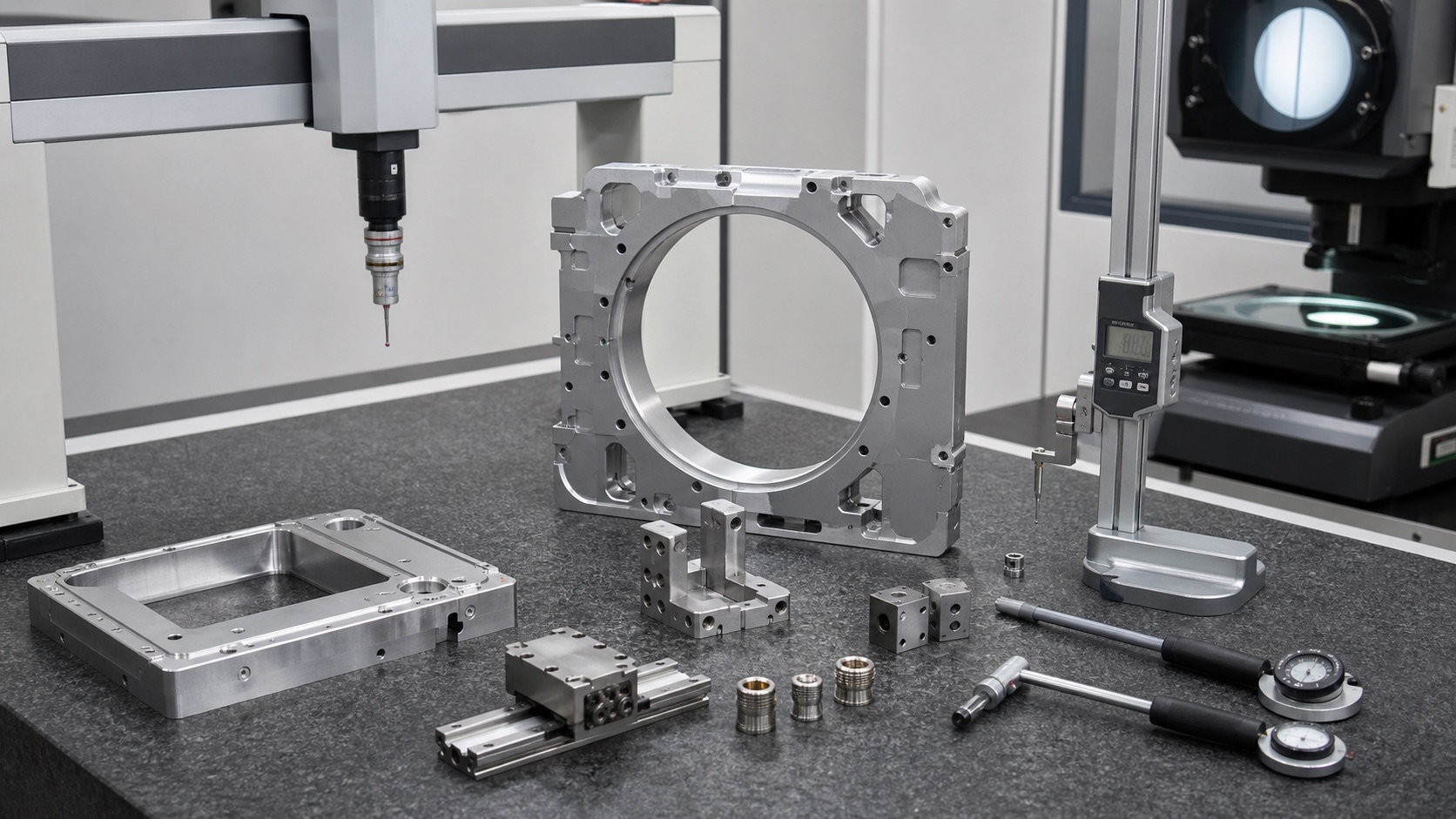
Detector housings often combine large windows, thin walls, pockets and cable-routing channels. Removing too much material in one operation can release stress and move the frame out of tolerance. A stable process usually uses staged roughing, stress-aware clamping, semi-finishing and final finishing from controlled datums. Cable channels need clean transitions and practical corner radii so covers fit without pinching wires. If weight reduction pockets are required, rib thickness and corner radii should be realistic enough for cutting tools and inspection probes.
Datum Control for Positioning Slides and Collimator Brackets
Positioning slides and collimator brackets must keep their relationship to sensor planes, beam paths or optical axes. The most important features are often not the largest features, but the datum pads, dowel holes, rail mounting faces, threaded inserts and precision bores. Five-axis machining can reduce setups for complex brackets, but datum strategy is still more important than machine capability alone. For repeatable assembly, it helps to define which surfaces are reference surfaces, which holes control alignment and which features are clearance only.
Inspection Planning for Imaging Equipment Parts
Inspection should confirm flatness, parallelism, perpendicularity, pocket depth, bore position, rail spacing, threaded feature quality and cosmetic condition. CMM inspection is useful for datum relationships, while optical measurement can check small slots or pocket edges. For prototype builds, a first article report helps engineering teams decide whether tolerances are realistic before freezing the design. If the component will be anodized or passivated, inspection planning should consider whether measurements are needed before finishing, after finishing or both.
Finishing, Clean Handling and RFQ Details
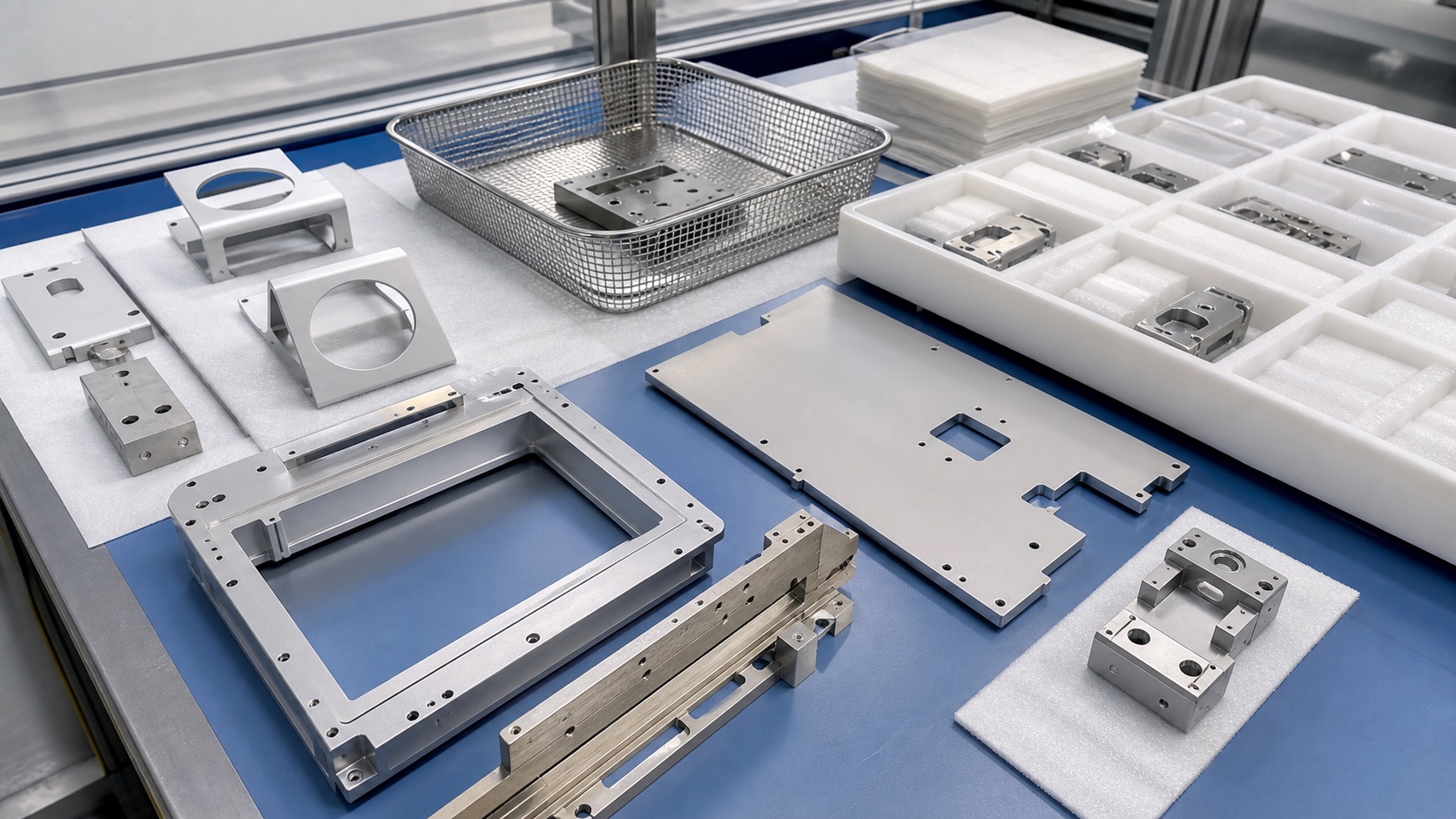
Medical imaging equipment parts often require deburring, anodizing, passivation, cleaning and protective packaging. Burrs can interfere with assembly or contaminate sensitive modules, and scratches on datum faces can affect calibration. Clean delivery does not replace the device maker's internal acceptance process, but it reduces incoming inspection problems. A strong RFQ should include 3D CAD, 2D drawings, material and finish requirements, expected quantities, critical datum features, inspection report needs, packaging rules and any restrictions related to shielding, optics, sensors or cable routing.
FAQ
What files are needed to quote detector housing components?
A 3D model, 2D drawing, material grade, finish requirement, quantity, critical datum features and inspection expectations are the most useful inputs.
Why is datum control important for imaging equipment parts?
Datum control keeps sensors, rails, collimators and brackets aligned so assembly and calibration remain repeatable.
Can thin-wall aluminum frames be CNC machined accurately?
Yes, but they need stress-aware toolpaths, stable fixturing, staged machining and final inspection of flatness and datum relationships.
Which features should be marked as critical?
Mark detector mounting faces, rail seats, dowel holes, collimator interfaces, threaded inserts, precision bores and any feature that controls alignment.
Should parts be inspected before or after anodizing?
Some dimensions may need checks both before and after anodizing, depending on coating thickness, tolerance and functional surface requirements.
What packaging helps protect precision imaging parts?
Foam separation, individual wrapping, clean bags, clear labels and protection of datum faces help prevent scratches and handling damage.
Email: tanghangyun@oemach.com