
Stainless steel CNC machining for optical instrument parts needs strict control of burrs, deformation and surface scratches. Unlike ordinary structural parts, final acceptance often depends on assembly feel, optical-path stability, edge condition and clean appearance.
Stainless steel is strong, corrosion resistant and visually stable, so it is used for optical lens mounts, retaining rings, thin-wall rings, guide sleeves, fixing seats and high-stability brackets. The challenge is that stainless steel is tough and work-hardens easily; poor tooling, clamping or deburring can leave small burrs or scratches.
OEMach treats optical stainless steel parts as final-state components. Low-stress clamping, rough/finish separation, microscopic deburring, CMM reinspection and anti-scratch packaging are planned together instead of stopping at the machine-off size.
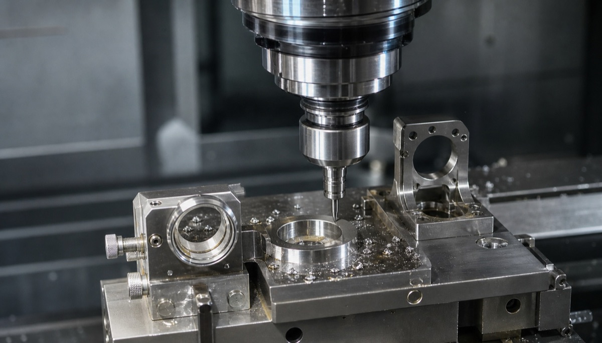
Risk Control Table
| Risk | Affected area | Possible consequence | Control method |
|---|---|---|---|
| Burrs | Small holes, slots, threads, thin edges and retaining-ring inner edges | Lens scratches, rough assembly feel or particle contamination | Optimize tool path, inspect under magnification, manual finishing and cleaning |
| Deformation | Thin rings, mount planes, windowed brackets and slender arms | Flatness drift, coaxiality change or uneven preload | Low-stress clamping, rough/finish separation and stress release when needed |
| Surface scratches | Visible faces, lens-adjacent faces and sealing faces | Appearance rejection or cleaning difficulty | Soft handling pads, separated trays and single-piece packaging |
| Tool marks | Optical mating faces, locating steps and slot bottoms | Unstable seating or changed optical angle | Control feed, tool wear and secondary finishing |
| Cleaning and packaging | Precision faces and small internal cavities | Chip, oil or particle residue entering assembly | Ultrasonic or wipe cleaning, anti-scratch packing and final review |
Burr Control Starts With Tooling and Tool Path
Because stainless steel has high toughness, burrs around small holes, narrow slots, thin edges and threads are harder to control than in aluminum. Optical parts are often close to lenses, filters, sensors and precision seating faces, so a small loose burr can scratch an optical element or create particle contamination.
Deburring cannot rely only on a final manual pass. Tool sharpness, cutting parameters, entry and exit position, chamfer strategy and cleaning method all influence the final edge. For micro holes, retaining-ring inner edges and lens-mount steps, magnified inspection is often needed.
The drawing or technical note should specify no sharp edges, no detachable burrs, critical hole-mouth chamfer range and whether microscopic inspection records are required. This makes the acceptance target clear before machining begins.
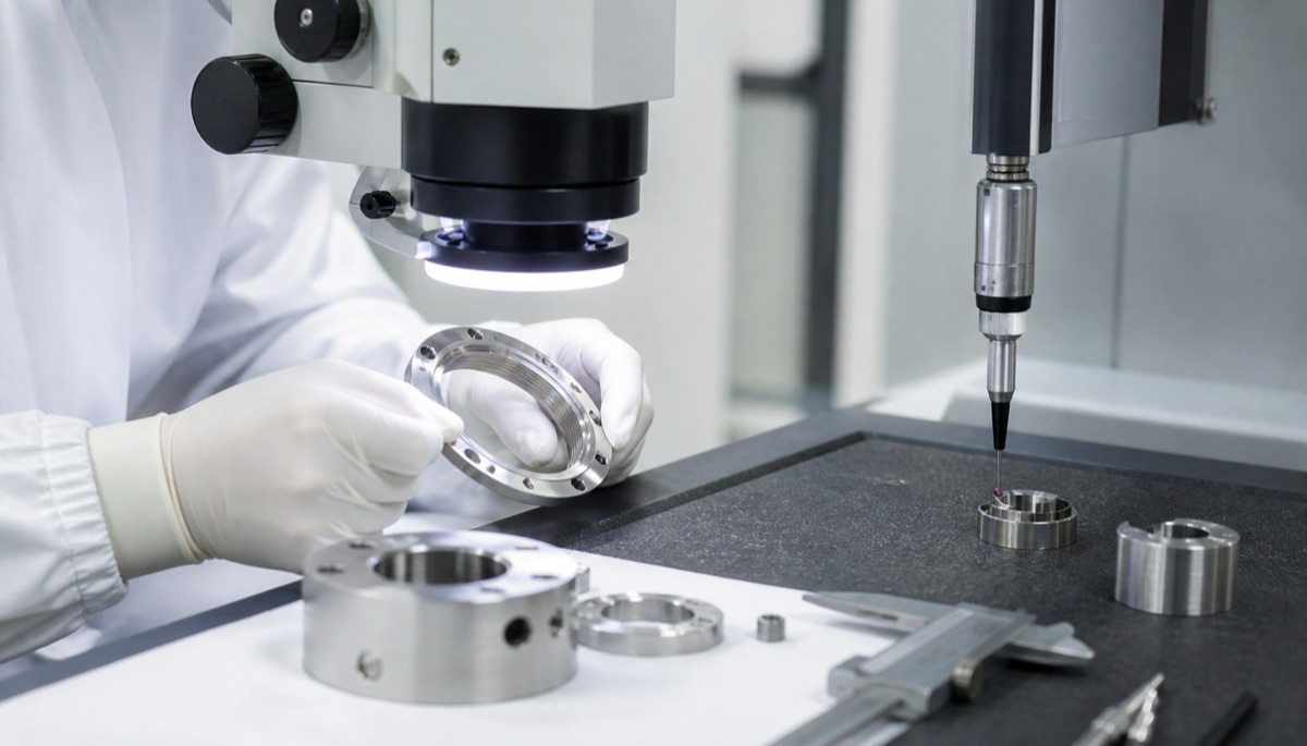
Thin-Wall and Windowed Structures Need Deformation Control
Optical stainless steel parts often include thin-wall rings, windowed brackets, retaining rings and compact lens mounts. Heavy cutting in one step, excessive clamping force or no separation between roughing and finishing can lead to ovality, warpage, flatness drift and coaxiality change.
Stainless steel has good rigidity, but machining stress and clamping deformation cannot be ignored. A part may look acceptable on the machine and then drift after unclamping or cleaning, especially in prototype and small-batch production.
OEMach commonly uses low-stress clamping, soft jaws or dedicated fixtures, staged machining and recutting of key surfaces for thin stainless steel parts. Critical features can be controlled tightly while general clearance profiles should not be over-specified.
Scratch Prevention Starts During Handling
Many appearance problems on optical stainless steel parts do not come from cutter marks. They happen during transfer, cleaning, inspection or packaging when parts contact metal tables, hard gauges, calipers or other components.
If a part has visible faces, sealing faces or lens-adjacent faces, process flow should use soft pads, compartment boxes, clean cloths or individual packaging to reduce direct contact. Inspection should also avoid dragging hard gauges across cosmetic or functional surfaces.
Instead of only writing no scratches, the RFQ should define the appearance area, allowed machining direction, unacceptable scratch or dent locations and required packaging protection.
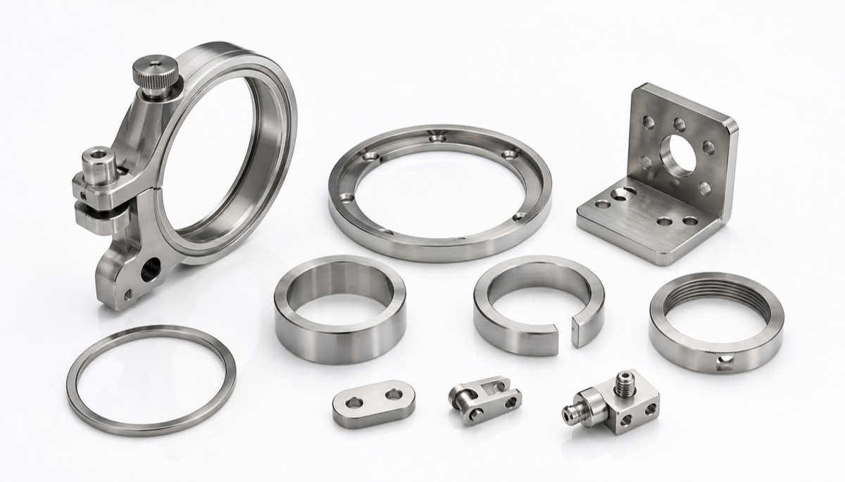
Five Manufacturing Controls
First, during DFM review, mark lens-adjacent faces, visible faces, locating datums and burr-sensitive edges so the part is not treated like a general stainless component.
Second, separate roughing and finishing. Use low-stress clamping for thin rings and windowed brackets to reduce release deformation.
Third, apply magnified burr review and cleaning to small holes, slots, threads and retaining-ring inner edges so chips do not enter optical assembly.
Fourth, protect visible and mating faces throughout inspection, cleaning, transfer and packaging with soft-contact methods.
Fifth, keep first-article records for dimensions, burr review, appearance inspection and packaging method, then use the same standard for repeat small batches.
OEMach Practice: Deliver the Final State
In one stainless steel retaining-ring and lens-mount project, the original requirement focused on dimensional conformance and no obvious scratches. During DFM review, OEMach identified lens-adjacent inner edges, small-hole burr risk and thin-ring deformation risk after release.
The final process used rough/finish separation, soft-jaw clamping, secondary finishing of critical seating faces, microscopic review of small holes and inner edges, cleaning and single-piece soft packaging. CMM reinspection confirmed coaxiality and flatness, while appearance areas were protected through transfer and packing.
This final-state approach helps reduce assembly risk because dimensional accuracy, edge condition, surface cleanliness and scratch prevention are managed together.
RFQ Questions Before Ordering
| Question | Why it matters |
|---|---|
| Which edges are close to lenses, sensors or sealing faces? | These edges may need magnified deburring |
| Is there thin-wall or windowed geometry? | Low-stress clamping and reinspection may be needed |
| Which faces are cosmetic or functional contact faces? | Scratch acceptance and handling rules depend on face type |
| Is cleaning, individual packaging, CMM or microscopic inspection required? | These items change delivery scope and cost |
FAQ
Why do stainless steel optical parts easily produce burrs?
Stainless steel is tough and work-hardens easily. Small holes, thin edges, slots and threads need tool-path control, deburring and magnified inspection.
Why do thin stainless steel parts deform?
Clamping force, cutting heat, internal stress and heavy cutting can cause thin rings, retaining rings and windowed brackets to move after release.
Where do surface scratches usually happen?
Besides machining, scratches often occur during inspection, cleaning, transfer, packaging or part-to-part contact.
Do optical stainless steel parts need CMM inspection?
If coaxiality, flatness, position or key assembly datums are involved, CMM or dedicated inspection reports are recommended.
Can OEMach support small-batch optical stainless steel parts?
Yes. OEMach supports stainless steel CNC machining, low-stress clamping, deburring, microscopic review, CMM inspection and anti-scratch packaging.
Summary
The difficulty of stainless steel optical part machining is not only material hardness. Burrs, deformation and scratches can directly affect assembly, optical-path stability and appearance acceptance. Thin rings, mounts, retaining rings, brackets and small-hole parts should connect tooling, clamping, deburring, cleaning, packaging and reinspection into one process.
Ready to get a quote for your CNC machined parts?
Submit your engineering drawings to qiancj@oemach.com. We support prototype sampling and small-batch production with strict tolerance control.