
Precision machining aluminum inserts for carbon fiber robot arms is not only about making an aluminum part to drawing size. The insert must work with a carbon fiber tube or shell, adhesive, threaded fasteners and joint modules as one stable composite connection.
Carbon fiber offers high stiffness at low weight, but it is not ideal for repeated threads, bearing seats, high-torque joints or local clamping loads. Aluminum inserts carry those functional interfaces while spreading load into the composite structure.
For this type of project, OEMach first confirms bonding zones, locating shoulders, threaded holes, assembly datums and surface-treatment needs. Only then should the team choose Al7075 or Al6061, 5-axis machining strategy, knurling or groove features and inspection method.
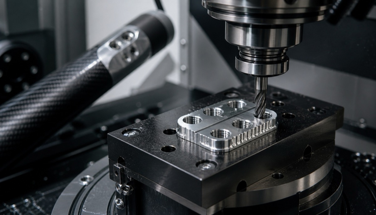
The Insert Must Serve Bonding and Assembly
| Control item | Function | Common risk | Process and inspection control |
|---|---|---|---|
| Outer diameter and locating shoulder | Position inside carbon fiber tube, sleeve or flange | Insert shifts or adhesive layer becomes uneven | Inspect OD, shoulder height and coaxiality from the same datum |
| Threads and through holes | End connection, joint flange or sensor installation | Unstable locking torque, rough threads or stripped threads | Use thread go/no-go gauges, trial assembly and torque feedback |
| Bonding or mechanical-lock features | Knurling, grooves, undercuts and roughened areas | Insufficient pull-out resistance or bonding interface failure | Control groove depth, edge burrs and surface roughness |
| Material and surface treatment | Al7075/6061, anodizing, blasting, masking or conversion coating | Strength, weight, bonding and appearance do not match | Separate cosmetic faces, bonding faces and conductive or masked faces |
| Inspection records | First article, small batch and repeat orders | First article works but later batches vary | Keep measured values, fixture basis, process notes and finish records |
Why Carbon Fiber Arms Need Metal Inserts
Carbon fiber is excellent for lightweight arm bodies, but direct threads in composite are usually not suitable for repeated assembly. Bearing seats, flange joints and sensor mounts also need local precision and load transfer that a composite wall alone may not provide.
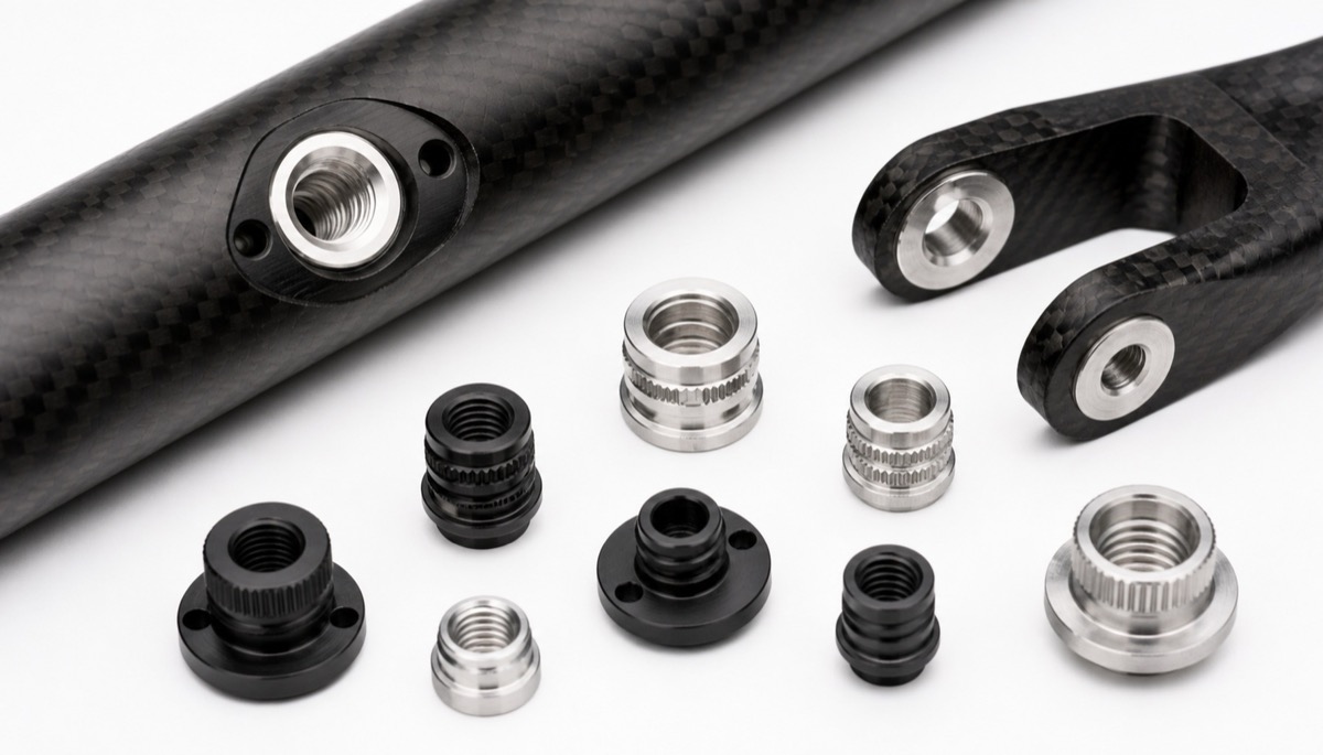
Common insert types include end flanges, threaded sleeves, bearing sleeves, sensor mounts, cable fixing points, joint connection sleeves and dowel seats. They may be small, but if their OD, step height, thread axis or surface condition is unstable, the entire arm can lose repeatability.
Material choice is a balance. Al7075 is useful when high strength is required, while Al6061 often gives a balanced route for machining and anodizing. The final decision should consider load, adhesive system, weight target and surface treatment.
Bonding Features Cannot Be Only Smooth Cylinders
If the insert outside surface is too smooth, the adhesive interface may rely mostly on chemical adhesion. Many carbon fiber arm designs add knurling, annular grooves, undercuts, micro-steps or roughened areas to increase bonding area and mechanical lock.
These features must be machined carefully. A groove that is too shallow may not help enough. Excess burrs can scratch the composite or disturb adhesive thickness. Unstable surface roughness can make bonding behavior vary between batches.
A good process separates the bonding zone from the assembly zone. The bonding zone may need roughening or grooves, while threads, bearing seats and locating shoulders remain precision-machined. If anodizing or blasting is used, bonding and masked areas should be defined clearly.
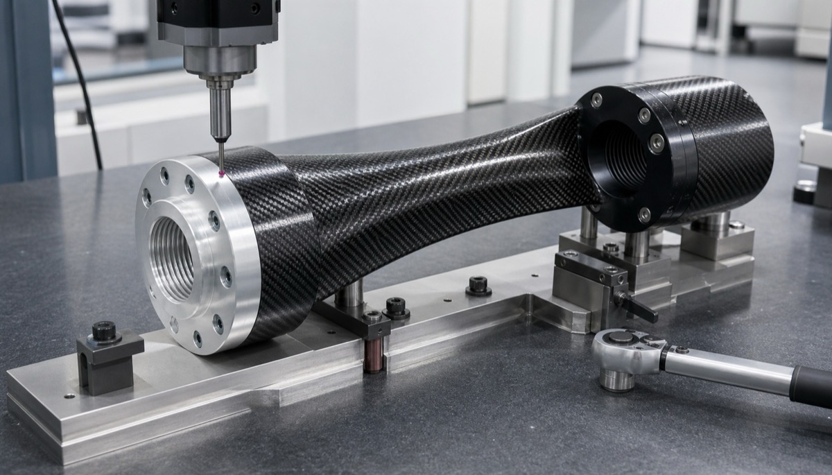
Threads and Datums Must Match Final Assembly
An insert often carries the threaded and locating interface for the robot arm. An end flange connects to a joint module, a threaded sleeve is assembled repeatedly, and a shoulder or dowel feature controls the relationship between the composite arm and the metal joint.
If machining only checks the thread size but ignores face runout, OD coaxiality or shoulder height, the thread may pass inspection while the assembled arm still becomes eccentric or locally stressed. Those stresses can transfer into the bonded composite interface.
First-article inspection should check OD, shoulders, end faces, thread quality and hole position together. Critical dimensions should be controlled according to function, while simple clearance areas do not need unnecessary tightness.
Five Process Controls
| Action | How to apply it | Benefit |
|---|---|---|
| Separate zones | Define bonding zone, assembly zone and cosmetic zone on the drawing | Prevents one surface treatment from hurting another function |
| Use one datum logic | Machine OD, shoulder, thread and end face from consistent datums where possible | Reduces coaxiality and runout problems |
| Control burrs on grooves | Deburr knurling, grooves and undercuts without rounding away their function | Protects the composite and adhesive layer |
| Select material by load | Review Al6061 and Al7075 against strength, weight, finishing and bonding needs | Avoids late material changes |
| Combine inspection and trial fit | Use CMM, thread gauges, torque feedback and assembly samples | Connects measured data to real assembly behavior |
How OEMach Reviews Composite Inserts
In a carbon fiber robot arm insert workflow, the customer initially supplied the outside shape and thread specification. OEMach reviewed the bonding length, knurled area, end-flange datum and black anodizing or masking requirements before finalizing the machining route.
The process used multi-axis machining to reduce datum transfers, kept the OD and end face aligned to the same datum logic, machined annular bonding grooves with controlled burr removal, and checked threaded holes with go/no-go gauges and trial parts.
This makes the insert more than a standalone CNC component. It becomes a functional interface that supports bonding strength, positioning accuracy and repeatable small-batch assembly.
RFQ Questions Before Ordering
| Question | Why it matters |
|---|---|
| Does the insert mainly carry pull-out, torque, shear or positioning load? | Load direction decides shape, wall thickness and bonding features |
| Does the bonding zone need knurling, grooves, blasting or masking? | The bonding surface should not be treated like a normal cosmetic surface |
| What is the final assembly datum: OD, end face, shoulder or thread axis? | Machining and inspection datums should match the assembly datum |
| Is first-article trial assembly or torque feedback required? | Assembly feedback helps stabilize later small-batch orders |
FAQ
FAQ
Why do carbon fiber robot arms need aluminum inserts?
Carbon fiber is suitable for lightweight structures, but threads, flanges, bearings and high-torque joints usually need metal inserts for positioning and load transfer.
What dimensions are most critical on an aluminum insert?
Common critical items include OD, locating shoulder, end-face perpendicularity, thread quality, hole position and bonding feature geometry.
Why add knurling or grooves to the bonding zone?
Knurling, grooves, undercuts and roughened surfaces increase bonding area and mechanical lock, helping resist pull-out and torque loads.
Should the insert use 6061 or 7075 aluminum?
Al6061 is balanced for machining and anodizing, while Al7075 provides higher strength. Selection should consider load, weight, bonding method and finishing route.
Can OEMach support small-batch insert machining?
Yes. OEMach supports CNC machining, 5-axis machining, thread inspection, surface-treatment review and CMM records for aluminum inserts used in carbon fiber robot arms.
Summary
Aluminum inserts for carbon fiber robot arms must be designed and machined as composite connection components. OD, shoulders, threads, stops, knurled or grooved bonding areas and surface treatment all need to support bonding strength, positioning accuracy and assembly repeatability.
Ready to get a quote for your CNC machined parts?
Submit your engineering drawings to qiancj@oemach.com. We support prototype sampling and small-batch production with strict tolerance control.