
In optical structural parts machining, surface treatment should not be treated as the final step that simply makes a part black or visually clean. Black anodizing, blasted anodizing, hard anodizing, passivation, black oxide and local masking can all change film thickness, bore condition, thread feel, contact faces, grounding areas and appearance consistency.
For lens mounts, optical platform adapters, camera housings and sensor brackets, the part that matters is the finished part. A CNC part may pass inspection before finishing, but after anodizing or blasting, a locating hole may become tight, a threaded ring may feel rough, or a contact face may no longer seat the same way.
OEMach reviews surface-treatment requirements during DFM, before cutting starts. The review separates cosmetic faces, precision datums, masked faces, conductive faces and post-finish inspection items so the supplier is not forced to make process decisions after machining.
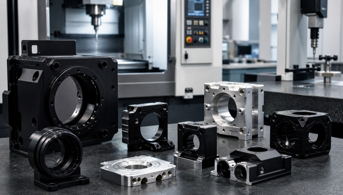
Where Surface Treatment Affects Optical Parts
| Control area | What changes | Common risk | Recommended control |
|---|---|---|---|
| Precision bores and threads | Film thickness, burr condition and thread flank feel | Bores become tight, screws feel rough, retaining rings do not run smoothly | Leave allowance when needed and verify after finishing with pin gauges, go/no-go gauges or trial assembly |
| Contact and locating faces | Flatness, surface roughness and seating condition | Optical axis angle changes or the assembly does not seat repeatably | Mask critical datums or inspect/rework them after finishing |
| Lens or sensor mounting areas | Film buildup and edge burrs around steps and counterbores | Uneven lens load or sensor tilt | Mark no-burr areas and include finished-state inspection |
| Cosmetic exterior faces | Color, brightness, blasting texture, water marks and scratches | Parts from the same device look inconsistent | Control material batch, pretreatment, blasting media, sealing and packaging |
| Conductive or grounding faces | Insulating oxide film and local contact resistance | Grounding or signal stability is affected | Define masking, film removal or conductive treatment on the drawing |
Film Thickness Enters the Dimension Chain
Anodizing forms a surface layer, and that layer does not appear only on easy outside faces. It can enter bore walls, steps, threads and counterbores. For a simple cover this may be harmless, but for optical structural parts, even a small finished-state change can affect the feel and repeatability of assembly.
Black anodizing is often used to reduce stray-light reflection, while hard anodizing is selected for wear resistance. The more important the film thickness is, the earlier the drawing should define whether dimensions are measured before or after finishing.
A practical drawing note should state which features may accept the film, which features need masking, and which bores, threads or contact faces must be inspected after surface treatment.
Masking Protects the Functional Datum
Optical parts usually combine appearance faces and functional datums. The outside may need uniform blasting and black anodizing, while a bottom face, dowel hole or grounding area may need conductivity, fit or a stable high-precision surface.
If these areas are processed in the same way, the result can be unpredictable. A lens mount bottom face may seat differently after a full anodize. A dowel hole may tighten. A grounding area may lose conductivity when it is fully oxidized.
Masking is therefore not an optional cosmetic detail. It is a way to protect the assembly datum. OEMach normally confirms cosmetic faces, masked faces, conductive faces and reinspection faces with the customer before production starts.
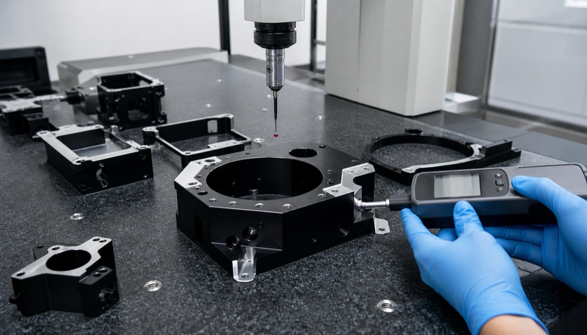
Appearance Consistency Starts Before Anodizing
Optical housings and visible structural parts are often sensitive to black anodizing appearance. Color shift, bright spots, water marks, uneven blasting and handling scratches can all affect customer acceptance, especially when multiple visible parts are assembled on the same instrument.
Appearance consistency cannot be solved by the anodizing supplier alone. Alloy grade, material batch, machining marks, blasting pressure, media condition, cleaning, sealing and packaging all influence the final look.
When a part has both cosmetic requirements and precision assembly requirements, the priority should be written clearly. Functional faces and exterior faces should not compete with each other in the process route.
Five Controls Before Machining
| Action | How to apply it | Why it matters |
|---|---|---|
| Separate face types | Classify cosmetic faces, functional faces, masked faces and conductive faces during DFM | Prevents a single finishing note from damaging fit or grounding |
| Confirm finished dimensions | Decide whether critical bores, threads and datums are specified before or after finish | Avoids first-article rework after anodizing |
| Bind finish parameters to batch | Keep material batch, blasting condition, color requirement and packaging standard together | Improves visible-part consistency |
| Inspect after finish | Check precision holes, threads, flatness and contact faces after anodizing or passivation | Verifies the state that will actually be assembled |
| Record first-article data | Keep before/after finish measurements and appearance notes | Makes repeat orders and small batches more stable |
How OEMach Handles Finished Optical Parts
In one optical camera housing workflow, the original requirement focused mainly on black anodizing and scratch-free appearance. During DFM, OEMach identified lens bores, a sensor seating face, locating pin holes and grounding areas that could be affected by film buildup.
The process separated cosmetic faces from masked and reinspection faces. Key bores were machined with the finish route in mind, and post-anodizing checks were carried out with gauges, CMM inspection and trial assembly. Exterior faces used controlled blasting and protective packaging to keep the batch visually consistent.
This approach is useful for low-volume optical parts because it reduces trial-and-error after finishing. The customer receives parts that are easier to assemble and more consistent on visible surfaces.
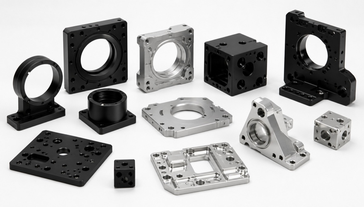
RFQ Questions Before Ordering
| Question | Why it helps |
|---|---|
| Are drawing dimensions required before finishing or after finishing? | The finished part is what enters the assembly |
| Which bores, threads, contact faces and grounding faces need masking or post-finish checks? | These features determine fit, seating and electrical contact |
| Does the visible surface need color, blasting texture, scratch level and packaging control? | Appearance consistency depends on the whole process, not only final inspection |
| Are material grade and batch requirements defined? | Different aluminum grades and batches can respond differently to anodizing |
FAQ
FAQ
Why confirm surface treatment before machining optical structural parts?
Because anodizing, blasting, masking and passivation can affect bores, threads, contact faces, conductive areas and final appearance. The finished state is the real assembly state.
Can black anodizing affect assembly accuracy?
Yes. Film buildup on bore walls, threads or locating faces can make fits tighter or change seating. Critical features should be masked or inspected after finishing.
Is appearance consistency only the anodizing shop's responsibility?
No. Material batch, machining marks, blasting parameters, cleaning, sealing and packaging all affect the final color and texture.
Which faces usually need masking?
Typical masking areas include precision bores, dowel holes, contact datums, grounding faces, threaded holes and lens or sensor seating areas.
Can OEMach control dimensions after surface treatment?
Yes. OEMach can support allowance planning, masking review, post-finish inspection and visual consistency control for optical structural CNC parts.
Summary
Surface treatment for optical structural parts directly affects assembly accuracy, cosmetic consistency and final acceptance. Anodizing film thickness, blasting texture, masking positions, conductive faces and post-finish inspection should be part of the drawing review before machining begins.
Ready to get a quote for your CNC machined parts?
Submit your engineering drawings to qiancj@oemach.com. We support prototype sampling and small-batch production with strict tolerance control.