
For optical instrument low-volume prototyping, the first question should not be only price or lead time. The first-article pass rate is usually determined by whether the tolerance, material and surface finish requirements are clear before the drawing is sent out.
These parts are common in lens mounts, sensor brackets, light-source mounts, optical platform adapters and small clamping structures. Quantities are often small, but the parts are sensitive to assembly datums, hole relationships, surface state and batch consistency.
If a drawing misses one critical tolerance, or if a material grade is substituted casually, the part may be machinable but still unstable during assembly, optical alignment or calibration.
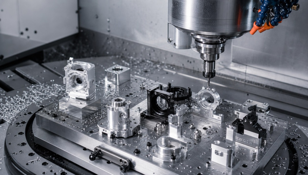
Three Requirements to Confirm Before Prototyping
| Requirement | What to confirm | Risk if unclear | Recommended wording |
|---|---|---|---|
| Tolerance | Critical holes, contact faces, dowel holes and optical-axis datums | General dimensions pass, but assembly or calibration is unstable | Grade critical positions and state the inspection datum |
| Material grade | Al6061, Al7075, PEEK, stainless steel, brass or other specified material | Strength, deformation, insulation or anodizing appearance does not match the design | Specify grade, temper/state and whether substitutions are allowed |
| Surface finish | Black anodizing, blasting, hard anodizing, passivation, blackening or masking | Film thickness tightens holes or changes contact faces | Define film thickness range, masking faces, cosmetic faces and post-finish checks |
| Inspection method | CMM, pin gauge, go/no-go gauge, roughness, flatness or position tolerance | Report datum and assembly datum do not match | Request actual measured values for first article, not only pass/fail |
| Quantity and revision | First-article quantity, small-batch quantity and repeat-order expectation | Process experience cannot be repeated in the next batch | Keep process, fixture, inspection and correction records |
Do Not Make the Whole Part Overly Tight
Many R&D drawings make every dimension tight because the team is worried about supplier variation. For optical instrument parts, the tightest control should usually be reserved for lens contact faces, dowel holes, sensor mounting faces, lens bores and optical-axis datums.
Ordinary outside edges, clearance slots and non-functional cosmetic faces do not always need the same tolerance level. Over-tightening every feature increases machining cost and inspection time without necessarily improving optical assembly stability.
A better approach is to classify dimensions by function. Use higher precision for optical datums and mating features, and keep standard tolerances for ordinary structure or clearance areas.
Material Affects Machining Route and Stability
Al6061 and Al7075 are common in optical instrument parts. Al6061 is stable for many brackets, mounts and housings and usually works well with anodizing. Al7075 provides higher strength, but thin-wall distortion, stress release and color consistency after anodizing should be considered early.
PEEK may be selected when insulation, low weight or chemical resistance is needed. It requires control of cutting heat and rebound, so it should not be machined with ordinary aluminum assumptions. Stainless steel, brass and titanium should be evaluated based on strength, weight, corrosion resistance and thermal behavior.
When material is changed late, the tooling, fixture, cutting parameters, surface treatment and inspection datum may all change. For low-volume prototyping, the drawing or RFQ should state whether alternative materials are allowed.
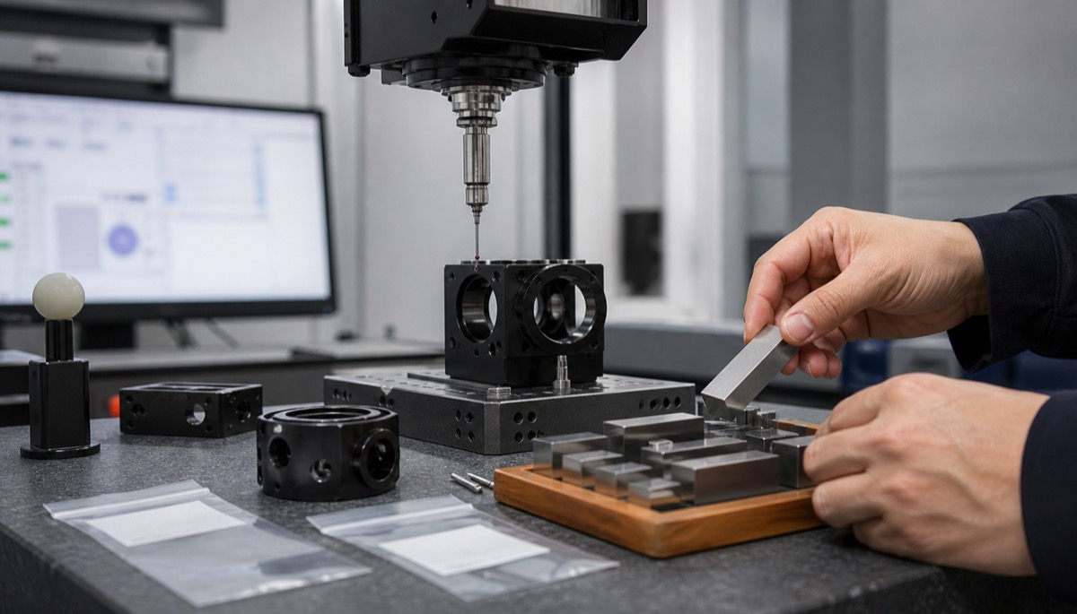
Surface Treatment Belongs in the Dimensional Chain
Optical instrument parts often need black anodizing, blasted anodizing, hard anodizing, passivation or matte finishing. These look like final appearance steps, but they can affect bore size, threads, contact-face roughness and assembly feel.
Black anodizing can help reduce stray-light reflection, but film growth inside precision holes and threads may make fits tighter. Blasting changes surface texture, and a critical contact face without masking may no longer behave the same in assembly.
Surface treatment requirements should therefore be confirmed before machining. Critical bores, locating faces, conductive faces and lens contact faces should be marked for masking or post-finish inspection when needed.
Five Actions for a Stable Prototype Batch
| Action | How to apply it | Why it helps |
|---|---|---|
| Run DFM review first | Separate critical holes, datums, cosmetic faces and clearance areas | Aligns machining datum with assembly datum |
| Grade critical tolerances | Avoid high precision everywhere; reserve it for optical datums and mating areas | Controls cost while protecting function |
| Evaluate material and finish together | Review Al6061, Al7075, PEEK, stainless steel and finishing effects together | Prevents late process changes |
| Keep first-article measured data | Record bore size, flatness, position, roughness and post-finish state | Makes repeat orders easier |
| Close the assembly feedback loop | Bring first-article issues back to drawing, process and inspection basis | Reduces repeated manual adjustment |
How OEMach Supports Optical Prototype Parts
In optical instrument prototype projects, OEMach starts with DFM review. The team identifies which dimensions affect the optical path, which features need graded tolerance control, which materials fit the finishing route and whether post-finish inspection is required.
In one optical sensor bracket workflow, the customer initially provided a 3D model and only a small number of outline dimensions. OEMach clarified the sensor contact face, locating-pin holes, black-anodizing masking areas and CMM datum before machining.
The process used multi-axis machining to reduce datum transfer, staged machining to control thin-wall distortion, and post-anodizing checks on locating features and contact faces. This kind of early review reduces first-article rework and makes the next low-volume batch more repeatable.
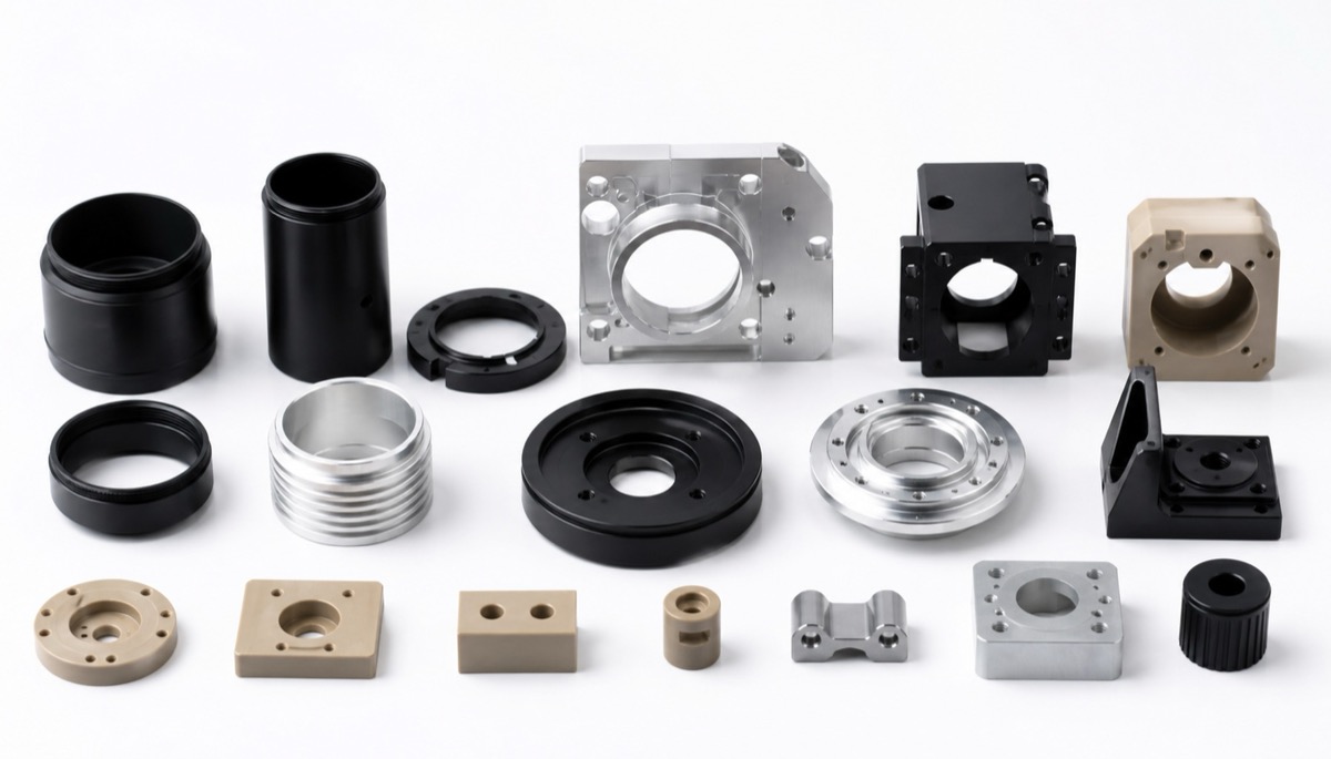
RFQ Checklist Before Sending Drawings
| Question | Why it matters |
|---|---|
| Does the 2D drawing clearly show critical dimensions, tolerances and datums? | A 3D model alone is often not enough for quotation and inspection |
| Are material grade, temper/state and substitution rules clear? | The supplier should not have to guess the material |
| Does the finish note include film thickness, color, masking, cosmetic faces and post-finish checks? | The final assembled state depends on the finish |
| Is a first-article CMM report, trial-fit note or measured-value sheet required? | Measured data helps future repeat orders |
FAQ
Why confirm tolerance before optical prototype machining?
Optical parts depend on optical axis, contact faces and locating-hole relationships. If critical tolerances are unclear, the first article may be machined but remain unstable during assembly or calibration.
Can the supplier choose the material?
The supplier can provide advice, but the drawing or RFQ should state the material grade, condition and whether substitutes are allowed.
Why does surface treatment affect dimensions?
Anodizing, blasting and passivation can change holes, threads, contact faces and surface roughness. Precision mating areas should define masking and post-finish inspection when needed.
Do optical prototype parts always need CMM inspection?
Critical optical datums, locating holes, mounting faces and GD&T items should usually be confirmed by CMM. Ordinary outside dimensions can often use standard gauges.
What should be sent for quotation?
Send STEP, 2D drawings, critical tolerances, datum notes, material, finish, quantity and inspection requirements.
Summary
Optical instrument low-volume prototyping should clarify key tolerances, material grade and surface treatment before machining starts. Tolerance determines assembly stability, material determines machining route and deformation risk, and surface treatment determines the final fitting state.
Ready to get a quote for your CNC machined parts?
Submit your engineering drawings to qiancj@oemach.com. We support prototype sampling and small-batch production with strict tolerance control.