
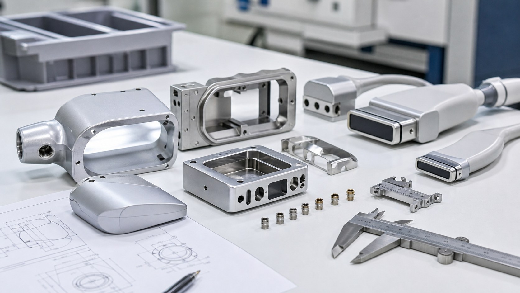
Ultrasound probes and medical imaging accessories place sensors, acoustic windows, cables and electronics into a compact handheld structure. CNC machining is useful for prototype housings, transducer frames and small-batch structural parts because it can control window flatness, thin walls, miniature threads and repeatable assembly datums before tooling investment.
Probe housings need stable sensor alignment
An ultrasound probe housing must hold the transducer stack, acoustic window, cable exit and cover interfaces in one repeatable geometry. Small errors in the window frame or sensor mount can change assembly preload or make sealing difficult. Drawings should define acoustic window datums, screw boss locations, cable strain relief features and cosmetic surfaces.
For quoting, send STEP files, 2D drawings, material grade, surface finish, assembly stack references and quantity. If the part mates with a lens, molded shell, PCB or cable boot, share those references so the machined structure can be checked as part of the assembly.
Material choice affects weight and finish
Aluminum alloys are common for prototype probe housings because they are light, stable and easy to machine into thin walls. Stainless steel can be used for transducer frames, wear plates or threaded inserts. PEEK or engineering plastics may be selected for insulation, lightweight fixtures or special testing.
Material notes should include grade, certificates, anodizing or passivation, cosmetic requirements and cleaning expectations. Prototype use, validation use and pilot production may require different levels of inspection and documentation.
Acoustic window flatness is a key feature
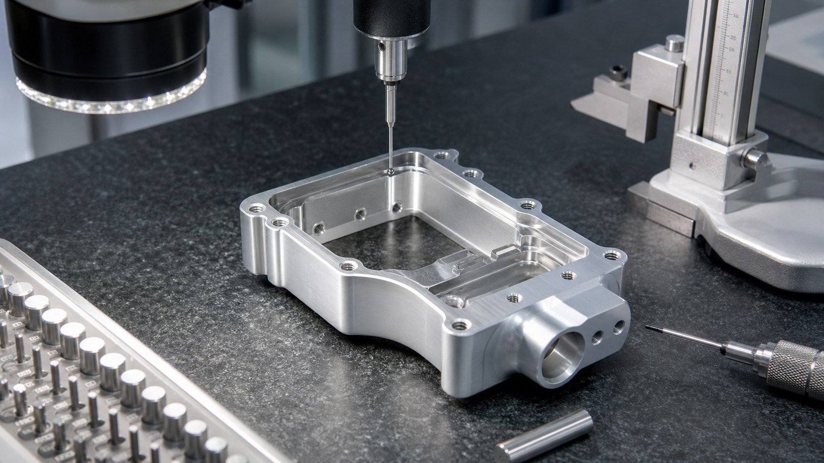
The acoustic window pocket needs controlled flatness, depth, corner radius and surface finish so the window, adhesive and transducer stack sit consistently. A warped face or sharp burr at the pocket edge can create assembly gaps or stress concentration.
Inspection should include flatness, pocket depth, step height, parallelism and optical review of corner quality. If bonding or sealing is planned, the drawing should define which surfaces must stay free from scratches or media residue.
Thin walls and curved shapes need careful fixturing
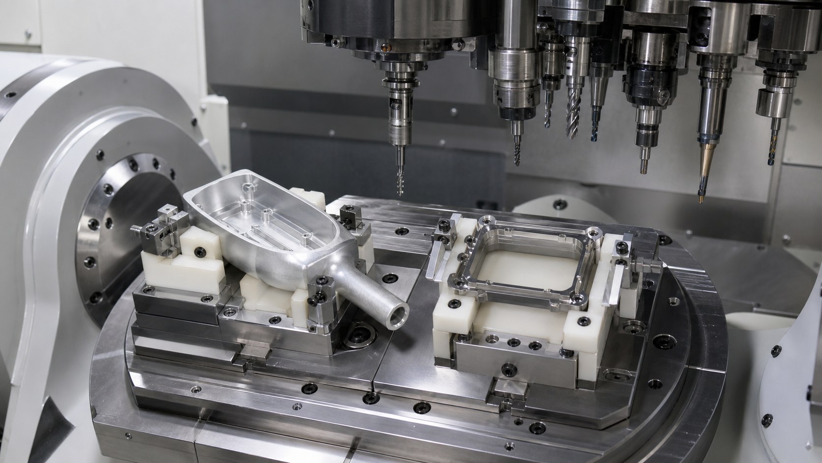
Probe housings often have ergonomic outer curves, thin ribs and deep pockets to save weight. These features can chatter or distort if held like a simple block. Soft jaws, nested supports, staged roughing and 3+2 or 5-axis access help keep walls stable.
A clear datum strategy is important when the part is flipped for backside machining. Functional features such as window frames and screw bosses should be controlled from the same reference system used during inspection.
Miniature threads and cable exits require detail control
Small M1.6, M2 or custom threaded inserts are common in probe assemblies, and cable exits often include smooth bores, shoulders or strain relief brackets. Burrs in these areas can damage wires, interfere with screw torque or create debris in the housing.
Drawings should call out thread depth, chamfer, edge break, torque target if known and protected cable-contact surfaces. Go/no-go gauges, torque-driver checks and microscope inspection help reduce assembly risk.
Finishing must protect functional surfaces
Anodizing, bead blasting, polishing and passivation can improve durability and appearance, but they may change small holes, threads and window pockets. Masking or post-finish checks are often needed around acoustic windows, screw bosses and cable features.
Burr-control notes should specify no loose burrs, controlled edge breaks and clean surfaces. Medical imaging prototypes should be cleaned so chips, polishing residue and abrasive media do not enter the assembly.
Clean packaging keeps small parts traceable
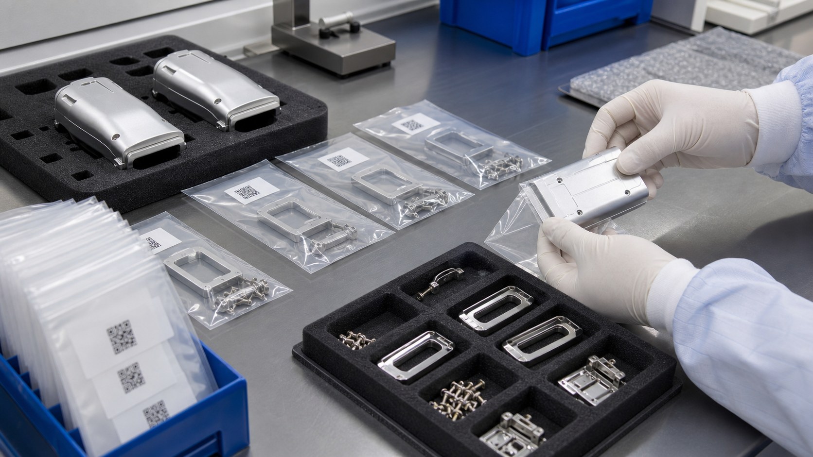
Probe housings, frames, screws and inserts are often revised quickly during development. Individual clean bags, foam trays, anti-static packaging and labels help engineers match each part to drawings, lots and inspection reports.
Packaging should identify part number, revision, material, quantity and inspection status. Separating cosmetic housings from small hardware protects surfaces during shipping and incoming inspection.
FAQ: Ultrasound Probe Housing CNC Machining
What files should I send for an ultrasound probe housing quote?
Send STEP files, 2D drawings, material grade, finish requirements, acoustic window details, cable exit features, thread callouts, assembly references and expected quantity.
Which materials are common for probe housings and mounts?
Aluminum is common for lightweight housings, stainless steel for transducer frames and inserts, and PEEK or engineering plastics for insulation or testing fixtures.
How is acoustic window flatness inspected?
Typical checks include flatness, pocket depth, step height, parallelism, corner quality and surface finish, often using CMM, height gauges and optical inspection.
Can thin-wall ultrasound housings be CNC machined accurately?
Yes. Soft jaws, nested supports, staged machining and stable datums help control thin ribs, ergonomic curves and deep pockets.
Why are miniature threads and cable exits risky?
Small threads and cable bores are sensitive to burrs, tool wear and finishing buildup. Gauges, torque checks and microscope inspection reduce assembly risk.
What quality documents can be supplied?
Common documents include material certificates, dimensional reports, CMM data, thread gauge records, surface finish data, inspection photos and packaging labels.
Email: tanghangyun@oemach.com