
The most underestimated requirement in optical lens mount CNC machining is often flatness. A lens mount can have correct outside dimensions, hole spacing and step height, yet still create lens tilt or imaging instability if the lens seating face or base face is not flat enough.
A lens mount is not an ordinary aluminum bracket. It locates the lens, transfers the assembly datum and holds optical posture after screws are tightened. When flatness is unstable, the lens may contact only locally, or the mount may bend when fixed to the platform.
For this reason, flatness should be reviewed together with the lens step, dowel holes, mounting base, surface treatment and inspection datum before quotation and machining begin.
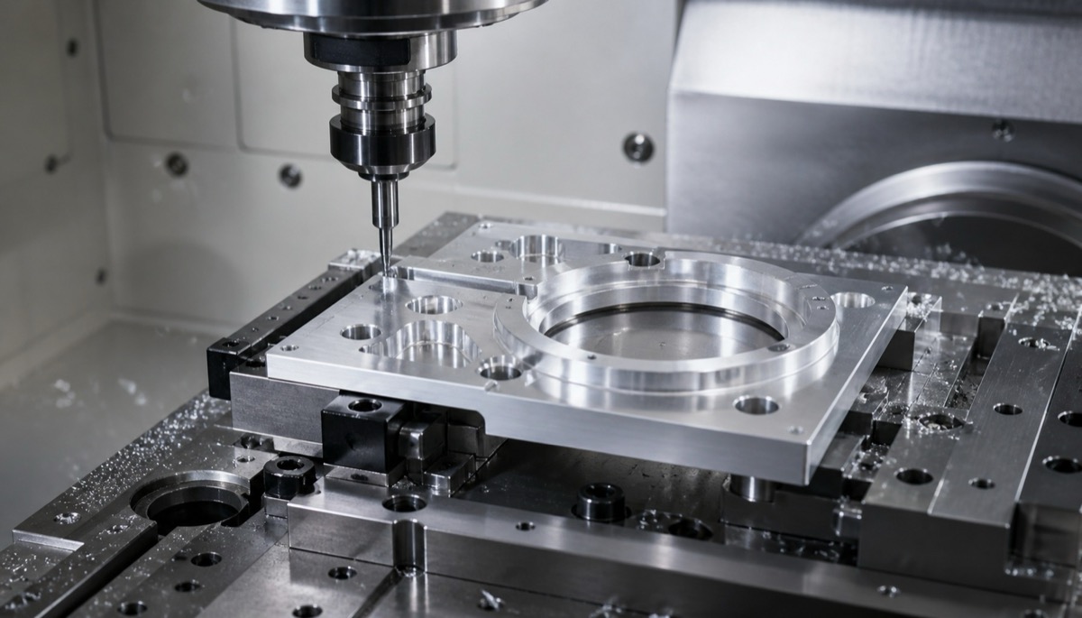
Flatness Areas That Affect Imaging Stability
| Control area | Function affected | Common problem | Machining and acceptance action |
|---|---|---|---|
| Lens seating face | Determines lens contact and posture | Local bow creates lens tilt or stress concentration | Inspect flatness after finishing; control roughness and burrs when needed |
| Mounting base face | Defines the relationship to platform or housing | Uneven base changes optical-axis angle after assembly | Separate roughing and finishing; use soft jaws or vacuum fixture; inspect from assembly datum |
| Lens locating step | Controls lens center and axial position | Unstable step height or corner burr affects contact | Check step height, concentric relationship and end-face quality together |
| Area around dowel holes | Controls repeat assembly accuracy | Hole position passes but contact face is unstable | Confirm position tolerance and flatness from the same datum |
| After anodizing or blasting | Changes surface roughness and film thickness | Critical contact areas become tight or less stable | Mask contact faces or inspect after finishing |
Why Flatness Becomes an Imaging Issue
Flat surfaces in optical mounts usually perform two jobs. One surface lets the lens, spacer or retainer sit evenly. Another surface transfers the mount to an external platform, camera housing or adjustment mechanism. Both jobs influence optical-axis angle and repeat assembly.
If the lens seating face is high in the middle or lifted at the edge, the lens can be locally loaded. If the base face is not flat, screws may pull the mount into a new shape after installation. The visible result can be edge sharpness variation, poor calibration repeatability or focal shift after temperature change.
Flatness cannot be judged by appearance or a simple caliper check. Critical lens mounts should be checked with CMM, height gauge, surface plate or dedicated fixture, and the inspection datum should match the face used in the real assembly.
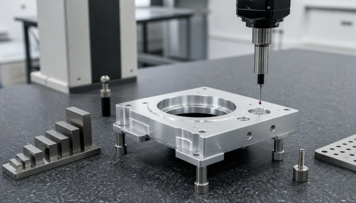
The Lens Locating Step Needs More Than Height
A locating step on a lens mount must control height, end-face flatness, corner radius, burr condition and its relationship to the center bore or locating holes. Step height can be correct while the local seating face is still not stable.
Al6061 and Al7075 are common for optical aluminum mounts. 6061 is easy to machine and anodize consistently, while 7075 offers higher strength but needs more attention to stress and finishing consistency. Thin walls, large pockets and dense hole patterns can all release stress after rough machining.
If the part requires black anodizing, blasting or matte treatment, critical lens seating faces and locating steps should be evaluated for masking or post-finish inspection. The final finished surface is what the lens actually contacts.
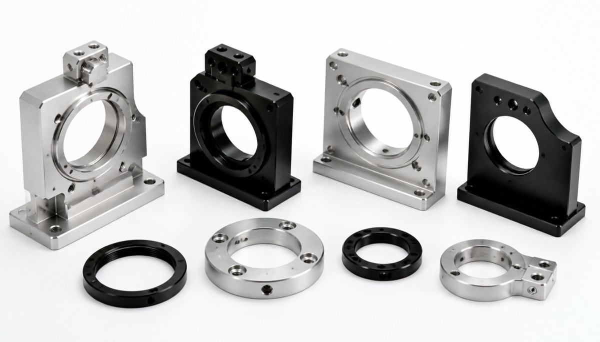
Five Controls for Lens Mount Machining
| Action | How to apply it | Why it helps |
|---|---|---|
| Define the real datum face | Do not treat an appearance face as the assembly datum | Keeps machining and inspection aligned with use |
| Separate roughing and finishing | Leave allowance and release stress before final face machining | Reduces flatness change after unclamping |
| Use low-stress fixturing | Apply soft jaws, vacuum, dowel support or controlled clamping force | Prevents local bending during machining |
| Check more than height | Inspect flatness, roughness, burrs, step height and post-anodizing state | Protects lens seating and assembly force |
| Report from one datum system | Link flatness, position tolerance and step height in the same inspection basis | Makes first-article tuning and repeat orders easier |
How OEMach Handles Optical Lens Mounts
For optical lens mounts, OEMach starts from the DFM review. The team identifies the lens seating face, mounting base, locating step and dowel-hole datum before choosing 5-axis machining, vacuum fixture, soft jaws or staged machining to control deformation.
In a typical lens mount workflow, rough machining leaves controlled allowance, the part is allowed to stabilize, and the lens seating face is finish-machined under a fixture that supports the real assembly datum. First-article inspection confirms flatness, hole position and step height together.
This method treats the lens mount as an optical datum component rather than a simple bracket. It helps reduce repeated calibration adjustments and makes small-batch delivery more consistent.
Questions Before Ordering
| Question | Why it matters |
|---|---|
| Which face is the true assembly datum? | Inspection from the wrong face can pass while assembly remains unstable |
| Does the lens seating face need flatness and roughness notes? | Step height alone does not cover local bow or burr risk |
| Are dowel-hole positions tied to the same datum face? | Correct hole spacing is not enough if datum transfer is inconsistent |
| Will critical contact faces be inspected after anodizing or blasting? | The finished state determines the real lens seating condition |
Common Mistakes
The first mistake is assuming that a mount is acceptable if it can be assembled. Optical mounts must assemble repeatedly with the lens in the same posture, not merely fit once.
The second mistake is treating flatness as a cosmetic item. For lens seating faces and base faces, flatness directly affects load, datum transfer and optical-axis angle.
The third mistake is inspecting only after CNC machining and ignoring surface treatment. For optical mounts, final acceptance should be based on the condition after anodizing, blasting or masking.
FAQ
Why is flatness important in optical lens mount machining?
Flatness affects lens contact, mounting datum and optical-axis posture. Poor flatness can create local lens stress, image tilt or unstable calibration.
What is the difference between flatness and parallelism?
Flatness evaluates one surface by itself. Parallelism evaluates whether two surfaces remain parallel. Optical mounts often need both reviewed against the assembly datum.
How should a lens locating step be inspected?
Check step height, face flatness, corner burrs, center relationship and the final state after surface treatment. Critical features may need CMM or dedicated fixtures.
Can anodizing affect lens mount flatness?
Anodizing mainly changes film thickness and surface condition, but blasting, pre-treatment, thin-wall stress and masking can affect critical contact faces. Post-finish inspection is recommended.
What should be sent for quotation?
Send STEP files, 2D drawings, datum scheme, flatness and roughness requirements, material, surface finish, quantity and inspection needs.
Summary
Flatness in optical lens mount CNC machining ultimately affects whether the lens sits reliably, the optical axis remains controlled and imaging stays repeatable. Buyers should review flatness, step height, hole position, surface treatment and inspection datum as one system before machining starts.
Ready to get a quote for your CNC machined parts?
Submit your engineering drawings to qiancj@oemach.com. We support prototype sampling and small-batch production with strict tolerance control.