
Optical barrel CNC machining is not just a matter of holding outside diameter, length and bore size. The functional result depends on whether the lens bore, outside locating diameter, end face and retaining-ring seat are built around one stable axis.
When coaxiality is poor, the optical center can shift. When end-face perpendicularity is weak, the lens can sit at a slight angle. When the bore is round but not controlled as a complete functional feature, assembly force, retaining-ring contact and focal-plane stability can all become inconsistent.
For buyers, the useful question is not only whether the drawing tolerance can be reached. It is whether the machining plan, fixture, surface treatment and inspection report protect the same optical datum from first article to repeat batch.
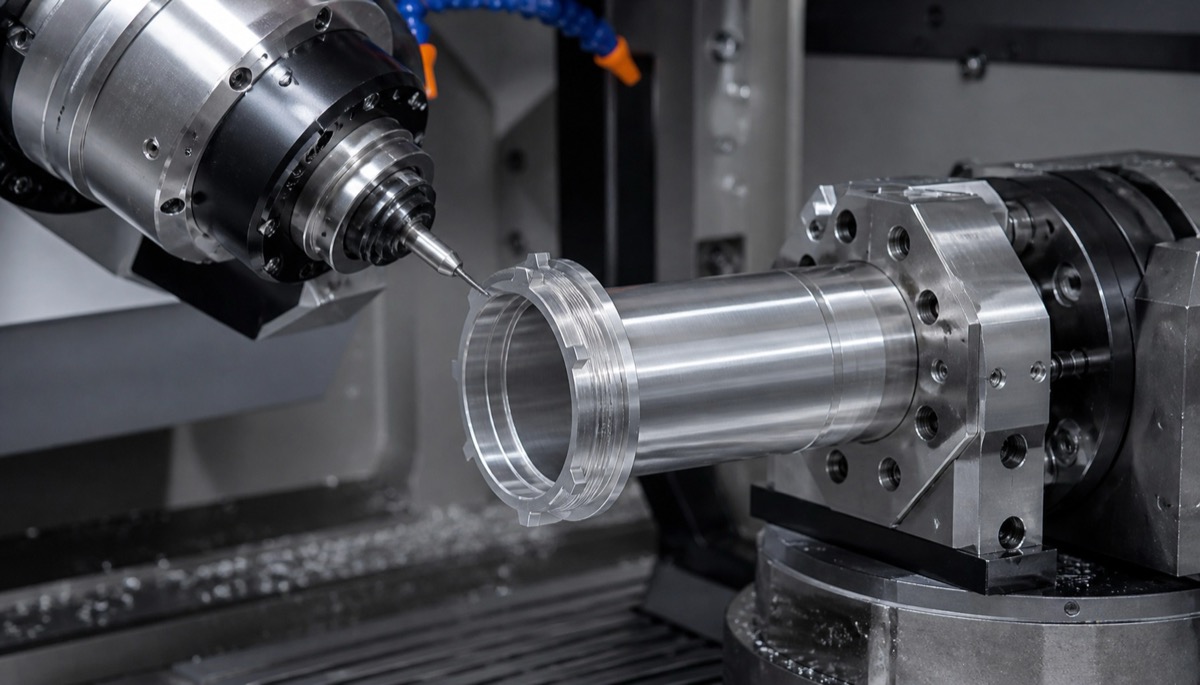
Key Accuracy Items for Optical Barrel Assembly
| Control item | Where it affects | Typical risk | Machining and inspection action |
|---|---|---|---|
| Coaxiality | Inner bore, outside diameter, threaded section and retaining-ring seat | Lens center shift and unstable optical axis | Machine critical cylindrical features in one setup when possible; check runout or coaxiality at first article |
| End-face perpendicularity | Lens seating face, retaining-ring face and connection face | Lens tilt, focal-plane drift and repeated shim adjustment | Build the end face from the bore axis; finish-turn or finish-mill critical faces |
| Bore precision | Lens seat, stepped bore and sleeve fit | Over-tight fit, loose fit or uneven press force | Control diameter, roundness, roughness and entrance burrs; record critical bore values |
| Thread and retaining-ring position | Internal thread, external thread and ring shoulder | Rough thread engagement or uneven locking force | Check tap-drill size, thread form, end runout and trial fit together |
| After surface treatment | Black anodizing, matte finish and masked datum faces | Film thickness tightens bores or changes contact faces | Define masking areas or inspect critical holes and faces after finishing |
Why Coaxiality Is the Main Line
The core function of an optical barrel is to keep lenses, spacers, retaining rings and external mounting features aligned along one optical axis. If the bore and the outer locating diameter are eccentric, each single dimension may still look acceptable while the actual optical axis has already moved.
Coaxiality errors often appear after multiple flips, datum transfers or heavy clamping on thin-wall tube features. A bore made in one setup and an outside locating diameter finished in another setup can pass separate size checks but fail as a working lens barrel.
A more stable route is to complete the critical bore, outer cylindrical surfaces, lens steps and reference end faces in one setup or under one unified datum system. Turn-mill machining, 4-axis or 5-axis auxiliary machining and CMM or runout inspection help confirm that the axis relationship has been protected.
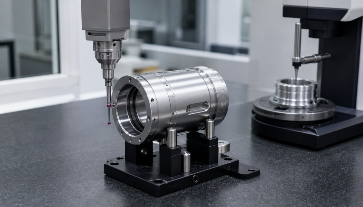
End Faces Control Lens Stress and Focal Plane
A lens is usually positioned by a seating shoulder, spacer face or retaining-ring face. If those faces are not perpendicular to the bore axis, one side of the lens may carry more load than the other side after tightening.
This issue is easy to miss during assembly because the lens may still fit and the part may look normal. Later, calibration can show focal-plane drift, image tilt or reduced stability after temperature changes. The root cause may be the barrel face, not the optical element itself.
For critical seating faces, flatness alone is not enough. The drawing and inspection plan should connect the face to the bore axis and, where necessary, include surface roughness, burr control and end-face runout requirements.
Bore Precision Is More Than Diameter
Optical barrel bore precision includes diameter, roundness, cylindricity, surface roughness, step height and entrance burr condition. A bore inside size tolerance can still create local lens pressure if roundness or edge quality is poor.
Al6061, Al7075, stainless steel and copper alloys are all used for optical barrel structures. For aluminum barrels with black anodizing or matte treatment, film growth on bores, threads and shoulders should be planned before machining and verified after finishing when the fit is critical.
A useful first-article report should retain actual bore values, coaxiality or runout values, perpendicularity data and trial-assembly notes. That history matters for low-volume repeat orders because the same datum logic must be repeated, not rediscovered.
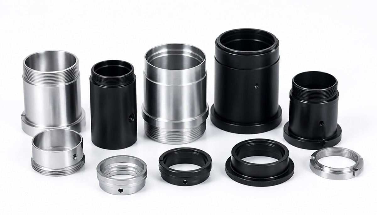
Five Controls Before Machining
| Action | How to apply it | Why it helps |
|---|---|---|
| Define the datum axis first | Set the bore, outside locating diameter and end faces under one process logic | Reduces repeated re-centering errors |
| Leave stable finishing allowance | Separate roughing and finishing for deep bores, thin walls and stepped features | Limits stress release and bore distortion |
| Inspect from one reference | Measure coaxiality, runout and perpendicularity using the same datum basis | Prevents conflicting interpretations of the report |
| Plan finishing effects | Mask or recheck critical bores, threads and contact faces after anodizing or matte finish | Confirms the final assembly state |
| Archive first-article data | Keep measured bore, runout, perpendicularity and trial-fit records | Makes repeat production more predictable |
How OEMach Reviews Optical Barrel Parts
For optical barrel projects, OEMach first reviews the locating relationship between the lens, retaining ring, outer housing and mounting platform. The team identifies which bore or cylindrical surface defines the optical axis before deciding on turn-mill machining, auxiliary 5-axis operations, bore finishing and inspection.
In a typical optical barrel workflow, key inner and outer diameters are completed under a unified datum strategy, thin-wall areas are rough- and finish-machined in stages, and the final lens seating face is re-cut after bore finishing. First-article checks then combine runout, end-face perpendicularity and CMM data to confirm consistency.
This approach adds detail during quotation, but it reduces trial-and-error at assembly. For small-batch optical barrels, clarifying the axis relationship early is usually more reliable than trying to correct lens tilt with shims later.
Questions Before Ordering
| Question | Why it matters |
|---|---|
| Which bore, outside diameter or end face defines the optical axis? | The supplier cannot prioritize the right datum if the drawing is silent |
| Do coaxiality, perpendicularity and bore precision need measured data? | Bore diameter alone cannot explain optical-axis behavior after assembly |
| Will black anodizing, matte finish or blasting affect critical fits? | The finished state is the real assembly state |
| Should lenses, spacers or retaining rings be trial-fitted at first article? | Trial-fit notes are valuable for low-volume repeat orders |
Common Mistakes
The first mistake is treating an optical barrel as a normal tube. A normal tube may focus on diameter and length; an optical barrel must also protect the relationship between bore, face, axis and retaining-ring position.
The second mistake is specifying bore size without face perpendicularity. If the lens seating face tilts, later assembly may not recover the optical path cleanly.
The third mistake is accepting pre-anodizing dimensions only. Black anodizing can affect bores, threads and end faces, so critical fitting areas should be verified in the final finished condition.
FAQ
Why is coaxiality important in optical barrel machining?
Because the barrel must keep lenses, spacers, retaining rings and external mounting features aligned around one optical axis. Poor coaxiality can shift the lens center and reduce imaging stability.
What does end-face perpendicularity affect?
It affects lens seating posture and axial load. A tilted face can lead to focal-plane drift, image tilt or repeated shim adjustment.
Is bore precision only about bore diameter?
No. Bore precision also includes roundness, cylindricity, roughness, entrance burrs, step height and the final state after surface treatment.
Is turning or milling better for optical barrel parts?
For cylindrical bores, outside diameters and end faces, turning or turn-mill machining is often more stable. Complex side holes or angled features may require 5-axis or milling operations.
What should be sent for quotation?
Send STEP files, 2D drawings, datum notes, critical coaxiality and perpendicularity requirements, material, surface treatment, quantity and inspection needs.
Summary
The core of optical barrel CNC machining is not making isolated dimensions look correct. It is keeping the lens assembly around one stable axis. Coaxiality, end-face perpendicularity and bore precision should be tied to the same datum system, inspection report and finishing plan.
Ready to get a quote for your CNC machined parts?
Submit your engineering drawings to qiancj@oemach.com. We support prototype sampling and small-batch production with strict tolerance control.