
In optical instrument CNC machining, a part can pass size tolerance and still create optical-axis instability. A bore diameter, slot width or step height inside tolerance only proves that one dimension is acceptable. It does not prove that a lens, sensor, prism or optical platform will remain aligned after assembly.
For optical components, flatness, perpendicularity, parallelism, position tolerance, coaxiality and runout often affect debugging more than ordinary outer dimensions. A lens mount may have a correct bore size, but if the bore axis is not perpendicular to the mounting face, the assembly can still show eccentricity, focal-plane drift or repeated shim compensation.
A better approach is to start from the optical datum. Before quoting or machining, define which face carries the optical axis, which holes locate the part, and which dimensions are only clearance or appearance features.
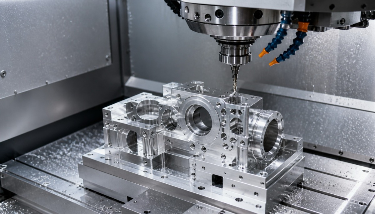
Size Tolerance and GD&T Must Be Reviewed Together
| Control item | Where it matters | Common problem | Confirmation action |
|---|---|---|---|
| Size tolerance | Bore, slot width, step height and outside dimensions | Single dimensions pass but optical axis shifts | Separate critical fit dimensions from clearance dimensions |
| Flatness | Lens mounting face, sensor contact face and platform datum | Unstable contact, shim compensation and calibration drift | Mark datum faces and require measured data |
| Perpendicularity / parallelism | Lens barrel axis, bracket side face and mounting-hole direction | Optical path angle error that cannot be tuned out | Define datum A/B/C and measurement direction |
| Position tolerance | Dowel holes, threaded holes and hole patterns | Holes assemble but center relationship is shifted | Identify functional holes and inspect from one datum scheme |
| Coaxiality / runout | Lens seats, retaining rings and sleeve parts | Lens or sensor center is eccentric | Inspect bore axis at first article; keep critical features in one setup when possible |
Why Optical Parts Are More Sensitive to GD&T
Robot structures usually emphasize motion and load. Optical instrument parts emphasize optical path, datum faces and repeat calibration. Even when outside dimensions are acceptable, a slightly warped mounting face can change the angle between a lens mount and a sensor.
Common parts include lens brackets, camera housings, laser mounts, prism clamps and optical platform adapter plates. These parts often combine large bores, thin walls, step faces and multiple mounting-hole groups. If machining requires repeated flipping or unstable datum transfer, hole relationships and face relationships are usually the first features to move.
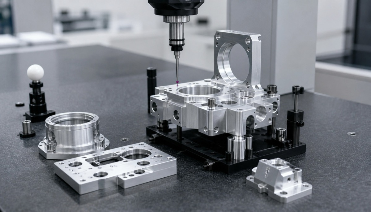
Five Controls to Prepare Before Machining
| Action | How to apply it | Why it helps |
|---|---|---|
| Classify functional dimensions | Grade lens bores, dowel holes and sensor faces separately from ordinary edges | Keeps tight tolerance where it protects the optical path |
| Reduce datum transfer | Use 4-axis, 5-axis or dedicated fixtures for critical holes and faces | Limits error from repeated clamping |
| Control thin-wall stress | Use staged machining, support ribs, soft jaws or vacuum fixtures | Prevents flatness change after unclamping |
| Protect optical datum faces | Design clamping around final assembly datum instead of only clamping force | Prevents dents, warp and reference mismatch |
| Plan post-finish inspection | Review critical holes and faces after anodizing, blasting, blackening or plating | Confirms the final delivered state, not only the machined state |
What to Check in the Inspection Report
For optical instrument parts, the most useful inspection report is not the one that only says pass. Buyers should check which datum was used to build the coordinate system, which holes have actual measured values, and how flatness, perpendicularity and coaxiality were evaluated.
At the first article stage, confirm bore size, hole position, mounting-face flatness, lens-bore coaxiality and critical-face perpendicularity. If the part will be reordered, keep the inspection datum, fixture method and correction history for future batches.
| Report item | Buyer focus | Reason |
|---|---|---|
| Datum scheme | Datum A/B/C must match assembly logic | A report from the wrong datum cannot explain optical debugging issues |
| Position tolerance | Actual values for functional holes | Prevents center-shift problems hidden by simple hole-size checks |
| Flatness | Mounting and sensor contact faces | Controls optical-axis and focal-plane stability |
| Perpendicularity | Bore axis to mounting face | Prevents lens tilt and repeated shim adjustment |
| Coaxiality / runout | Lens seat, ring and sleeve features | Keeps optical center aligned |
| Post-finish check | Critical features after anodizing or plating | Confirms final dimensions after surface treatment |
How OEMach Approaches Optical CNC Parts
For optical instrument parts, OEMach first reviews the part function in the optical system. The team identifies the optical datum, sensor contact face, locating holes and critical bores before deciding which features need 0.005 mm to 0.02 mm level control and which GD&T items should be confirmed by CMM data.
In one lens-mount type workflow, key bores, locating holes and mounting faces were treated as critical control zones. 5-axis machining reduced datum transfer, while soft jaws and staged machining supported thin-wall areas. First-article CMM data then confirmed position, perpendicularity and flatness before moving to repeat parts.
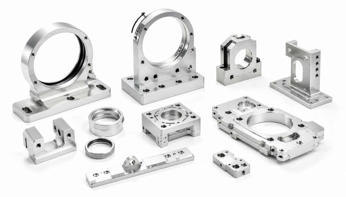
Questions Before Ordering
| Question | Why it matters |
|---|---|
| Which face or hole defines the optical datum? | Machining datum and assembly datum should not conflict |
| Which GD&T items need CMM inspection? | Flatness, perpendicularity, position and coaxiality cannot be confirmed by calipers alone |
| Which dimensions are functional and which are clearance? | Avoids over-tightening every feature and increasing cost |
| Will surface treatment happen before final inspection? | Black anodizing, blasting or nickel plating can affect holes and contact faces |
| Will first-article values be archived? | Repeat orders need the same inspection basis |
FAQ
Why is size tolerance not enough for optical instrument CNC parts?
Optical parts depend on optical axis, focal plane and mounting datum. Size tolerance checks a single dimension, while GD&T describes the relationship between holes, faces and axes.
Which GD&T items are most important for optical parts?
Flatness, perpendicularity, parallelism, position tolerance, coaxiality and runout are common priorities. The final choice depends on how the lens, sensor or optical platform is assembled.
Do optical CNC parts always need CMM inspection?
Critical optical datum faces, lens bores, locating holes and sensor contact faces should usually be checked by CMM. Ordinary clearance features can often use standard gauges.
Should 0.005 mm tolerance be applied everywhere?
No. Very tight tolerance should be reserved for critical fits and optical datum features. Ordinary outside dimensions should stay function-based.
What should be included in the RFQ?
Send STEP files, 2D drawings, datum scheme, critical GD&T notes, material, surface treatment, quantity and inspection requirements.
Summary
Optical instrument CNC machining should not be judged by size tolerance alone. The features that protect optical path stability are often flatness, perpendicularity, position, coaxiality and a matching inspection datum. Clarifying optical datums and CMM reporting before machining can reduce first-article debugging and make small-batch delivery more repeatable.
Ready to get a quote for your CNC machined parts?
Submit your engineering drawings to qiancj@oemach.com. We support prototype sampling and small-batch production with strict tolerance control.